Correção IME 2027 · Português e InglêsAcompanhe a resolução de cada questão da 2ª fase, ao vivoAcompanhar
IA ao vivo / ITA 2027 · 2ª fase · Física

COMPARE OS RACIOCÍNIOS

Questão 7 (Física)

Questão discursiva: a banca não divulga gabarito oficial. ← 6 (Física) 8 (Física) →

A questão

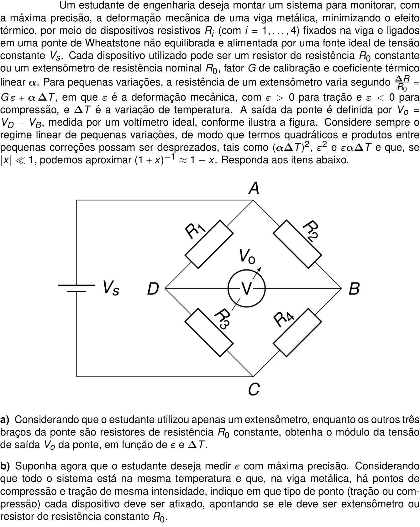
Texto de apoio da questão 7 (Física) Questão 7 (Física)

Resposta de referência

a) |V_o|\simeq\frac{V_s}{4}|G\varepsilon+\alpha\Delta T|. b) Usar quatro extensômetros, com R_1 e R_4 em compressão e R_2 e R_3 em tração, ou o inverso. As contribuições mecânicas se somam e o efeito térmico se cancela em primeira ordem, com |V_o|\simeq V_s|G\varepsilon|.

Segundo a resolução dos cursinhos Farias Brito e Poliedro. A banca não publica gabarito das questões discursivas.

Respostas das IAs

GPT-6 Astra

Respondeu · bate com a resposta de referência dos cursinhos

a) |V_o|\simeq \dfrac{V_s}{4}|G\varepsilon+\alpha\Delta T|; b) quatro extensômetros, R_1 e R_4 em compressão e R_2 e R_3 em tração (ou todos invertidos), com |V_o|\simeq V_s|G\varepsilon| e compensação térmica em primeira ordem.

levou 22 s

Como pensou

Tomando V_C=0 e V_A=V_s, como o voltímetro ideal não conduz corrente, os divisores de tensão fornecem

V_D=V_s\frac{R_3}{R_1+R_3}, \qquad V_B=V_s\frac{R_4}{R_2+R_4}.

Escrevendo R_i=R_0(1+\delta_i), com |\delta_i|\ll1, temos, em primeira ordem,

\frac{R_3}{R_1+R_3} =\frac{1+\delta_3}{2+\delta_1+\delta_3} \simeq\frac12+\frac{\delta_3-\delta_1}{4}.

Analogamente,

\frac{R_4}{R_2+R_4}\simeq\frac12+\frac{\delta_4-\delta_2}{4}.

Portanto,

\boxed{V_o\simeq\frac{V_s}{4} \left(-\delta_1+\delta_2+\delta_3-\delta_4\right)}.

a) Apenas um extensômetro

Se o extensômetro estiver em R_1,

\delta_1=G\varepsilon+\alpha\Delta T, \qquad \delta_2=\delta_3=\delta_4=0.

Assim,

V_o\simeq-\frac{V_s}{4}(G\varepsilon+\alpha\Delta T).

A escolha de outro braço pode alterar apenas o sinal da saída. Logo, o módulo pedido é

\boxed{|V_o|\simeq\frac{V_s}{4}\left|G\varepsilon+\alpha\Delta T\right|}.

b) Configuração de máxima precisão

Para maximizar a sensibilidade à deformação, devem ser utilizados quatro extensômetros, posicionados de modo que suas contribuições mecânicas se somem na saída.

Denotando por \varepsilon>0 o módulo das deformações, uma configuração adequada é:

Dispositivo Tipo Ponto de fixação
R_1 Extensômetro Compressão: -\varepsilon
R_2 Extensômetro Tração: +\varepsilon
R_3 Extensômetro Tração: +\varepsilon
R_4 Extensômetro Compressão: -\varepsilon

Nessa configuração,

\delta_1=\delta_4=-G\varepsilon+\alpha\Delta T, \qquad \delta_2=\delta_3=G\varepsilon+\alpha\Delta T.

Substituindo na expressão da saída,

V_o\simeq\frac{V_s}{4} \left[2(G\varepsilon+\alpha\Delta T) -2(-G\varepsilon+\alpha\Delta T)\right],

resultando em

\boxed{V_o\simeq V_sG\varepsilon}.

O efeito térmico cancela-se em primeira ordem, enquanto as quatro contribuições mecânicas se somam, dando sensibilidade quatro vezes maior que a de um único extensômetro. Também é possível inverter todas as posições de tração e compressão, alterando apenas o sinal de V_o.

Resposta final: a) |V_o|\simeq \dfrac{V_s}{4}|G\varepsilon+\alpha\Delta T|; b) quatro extensômetros, R_1 e R_4 em compressão e R_2 e R_3 em tração (ou todos invertidos), com |V_o|\simeq V_s|G\varepsilon| e compensação térmica em primeira ordem.

GPT-6.1 Sol

Respondeu · bate com a resposta de referência dos cursinhos

a) \displaystyle |V_o|=\frac{V_s}{4}|G\varepsilon+\alpha\Delta T|; b) todos extensômetros: R_1,R_4 em compressão e R_2,R_3 em tração (ou vice-versa), com \displaystyle |V_o|=V_s|G|\varepsilon, sendo \varepsilon>0 o módulo da deformação.

levou 19 s

Como pensou

Tomando V_C=0 e V_A=V_s, como o voltímetro é ideal, não passa corrente entre D e B. Assim, pelos divisores de tensão,

V_D=V_s\frac{R_3}{R_1+R_3}, \qquad V_B=V_s\frac{R_4}{R_2+R_4}.

Escrevendo R_i=R_0(1+\delta_i), com |\delta_i|\ll1, temos

\frac{R_3}{R_1+R_3} =\frac{1+\delta_3}{2+\delta_1+\delta_3} \approx\frac12+\frac{\delta_3-\delta_1}{4}.

Analogamente,

\frac{R_4}{R_2+R_4} \approx\frac12+\frac{\delta_4-\delta_2}{4}.

Portanto, em primeira ordem,

\boxed{V_o=\frac{V_s}{4}(-\delta_1+\delta_2+\delta_3-\delta_4)}.

a)

Se o único extensômetro ocupar, por exemplo, a posição R_1,

\delta_1=G\varepsilon+\alpha\Delta T, \qquad \delta_2=\delta_3=\delta_4=0.

Logo,

V_o=-\frac{V_s}{4}(G\varepsilon+\alpha\Delta T).

A escolha de outro braço pode inverter o sinal, mas não altera o módulo:

\boxed{|V_o|=\frac{V_s}{4}\left|G\varepsilon+\alpha\Delta T\right|}.

b)

Para obter a máxima sensibilidade à deformação, devem-se usar quatro extensômetros, de modo que suas contribuições mecânicas se somem na expressão de V_o.

Denotando por \varepsilon>0 o módulo da deformação, uma configuração é:

  • R_1 e R_4: extensômetros em pontos de compressão, com deformação -\varepsilon;
  • R_2 e R_3: extensômetros em pontos de tração, com deformação +\varepsilon.

Como todos estão à mesma temperatura,

\delta_1=\delta_4=-G\varepsilon+\alpha\Delta T, \qquad \delta_2=\delta_3=G\varepsilon+\alpha\Delta T.

Substituindo,

V_o=\frac{V_s}{4} \left[-(-G\varepsilon+\alpha\Delta T) +(G\varepsilon+\alpha\Delta T) +(G\varepsilon+\alpha\Delta T) -(-G\varepsilon+\alpha\Delta T)\right],

de onde

\boxed{V_o=V_sG\varepsilon}.

Assim, o efeito térmico cancela-se em primeira ordem e as quatro contribuições mecânicas somam-se, dando a máxima sensibilidade. A troca de todos os pontos de tração pelos de compressão apenas inverte o sinal da saída.

Resposta final: a) \displaystyle |V_o|=\frac{V_s}{4}|G\varepsilon+\alpha\Delta T|; b) todos extensômetros: R_1,R_4 em compressão e R_2,R_3 em tração (ou vice-versa), com \displaystyle |V_o|=V_s|G|\varepsilon, sendo \varepsilon>0 o módulo da deformação.

GPT-6 Luna

Respondeu · bate com a resposta de referência dos cursinhos

a) \displaystyle |V_0|\simeq \frac{|V_s|}{4}|G\varepsilon+\alpha\Delta T|; b) usar quatro extensômetros: R_2,R_3 em tração e R_1,R_4 em compressão (ou vice-versa), obtendo |V_0|\simeq |V_s|G\varepsilon.

levou 17 s

Como pensou
**Calculating with extensometers** I need to carefully derive an equation for measuring an arbitrary position using one extensometer while three are fixed. The output seems to depend on symmetry and sensitivity factors, as location may vary with expressions based on arm placement. I’m calculating linear changes across R0, with voltage nodes associated with each variable. The output will involve various equations for different arms, and although the process is a bit intricate, I should maintain clarity in the measurements I’m trying to capture.**Evaluating gauge measurements** I’m wondering if I need to distinguish between gauge arms, especially since they might all be set to the same temperature. I need to maximize measurements while minimizing thermal effects. With four active gauges in a full bridge, I want to ensure that strain signals add up and temperature effects cancel out. It's essential to assign correct gauge types and locations for tension or compression and determine how the bridge output responds to each gauge's signs. I’m trying to derive the relationship in the output based on those variables!**Exploring extensometers and thermal effects** I'm considering the tradeoff of using two extensometers for tension and compression combined with two fixed resistors to form a half bridge for thermal effects. If the temperature is the same for both gauges, I need to ensure their coefficients can cancel out thermal effects while adding mechanical strain. Each gauge has to be positioned properly to achieve the best sensitivity, ideally maximizing output while minimizing thermal impact. All four gauges seem to provide the best response.**Analyzing output sensitivity** I'm evaluating the output versus Gε, noting that each term contributes equally when divided by four. For temperature cancellation, I can assign tension to R1 and R4 while R2 and R3 receive compression, yielding a consistent output. I’m considering if fixed resistors could work, but ideally, all four positions should use gauges. While I could use pairs under tension and compression with resistors, maximum sensitivity would best be achieved with a full bridge setup. Just need to remember that temperature must remain consistent for proper results!

a)

Tomando A como o potencial V_s e C como referência, os potenciais nos pontos médios são

V_D=V_s\frac{R_3}{R_1+R_3}, \qquad V_B=V_s\frac{R_4}{R_2+R_4}.

Escrevendo R_i=R_0(1+\delta_i) e mantendo apenas termos de primeira ordem,

V_0=V_D-V_B \simeq \frac{V_s}{4}\left(-\delta_1+\delta_2+\delta_3-\delta_4\right).

Com um único extensômetro, sua variação relativa é

\delta=G\varepsilon+\alpha\Delta T,

e as outras três variações são nulas. Qualquer que seja o braço onde se coloque o extensômetro, o módulo da saída é, portanto,

|V_0|\simeq \frac{|V_s|}{4}\left|G\varepsilon+\alpha\Delta T\right|.

b)

Para que as variações térmicas se anulem, podemos usar extensômetros nos quatro braços. Por exemplo, coloquemos R_2 e R_3 em pontos sob tração, e R_1 e R_4 em pontos sob compressão, todos com a mesma intensidade de deformação \varepsilon>0.

Assim,

\delta_2=\delta_3=G\varepsilon+\alpha\Delta T, \qquad \delta_1=\delta_4=-G\varepsilon+\alpha\Delta T.

Substituindo na expressão da saída,

V_0\simeq \frac{V_s}{4} \left[-\delta_1+\delta_2+\delta_3-\delta_4\right] =V_sG\varepsilon.

As contribuições térmicas se cancelam, enquanto as mecânicas se somam. A disposição inversa — tração em R_1,R_4 e compressão em R_2,R_3 — também funciona, invertendo o sinal da saída.

Resposta final: a) \displaystyle |V_0|\simeq \frac{|V_s|}{4}|G\varepsilon+\alpha\Delta T|; b) usar quatro extensômetros: R_2,R_3 em tração e R_1,R_4 em compressão (ou vice-versa), obtendo |V_0|\simeq |V_s|G\varepsilon.

Claude Fable 5.1

Respondeu · bate com a resposta de referência dos cursinhos

a) |V_o| = (V_s/4)|Gε + αΔT|; b) todos os quatro dispositivos devem ser extensômetros: R₂ e R₃ em pontos de tração e R₁ e R₄ em pontos de compressão (ou o inverso), resultando V_o = V_s G ε, sem efeito térmico.

levou 24 s

Como pensou
I'm setting up the bridge with VC as reference ground and VA at supply voltage, deriving VD and VB from the voltage divider ratios, then computing Vo as their difference. For part (a), I consider a single strain gauge replacing R1 with R0(1+δ), where δ combines the strain and thermal effects, and I linearize the expression to find that the output magnitude is Vs|Gε + αΔT|/4, regardless of which arm holds the gauge. For part (b), I'm working through a full bridge where all four resistors are active gauges with their own δi deviations, linearizing each divider term and combining them to show that Vo reduces to (Vs/4)(δ2 + δ3 − δ1 − δ4), which is the configuration that maximizes sensitivity while canceling common temperature effects. Since all four δi contain the same αΔT term, it cancels completely in the combination, leaving Vo = (VsG/4)(ε2+ε3−ε1−ε4). Maximum output occurs when gauges on adjacent arms experience opposite strain types—tension on R2,R3 and compression on R1,R4 (or the reverse)—giving |Vo| = VsGε with full temperature compensation.

Montagem do circuito. A fonte está ligada entre A e C; tomando V_C = 0 e V_A = V_s, os ramos A–D–C (R₁, R₃) e A–B–C (R₂, R₄) são divisores de tensão:

V_D = V_s·R₃/(R₁+R₃), V_B = V_s·R₄/(R₂+R₄)

V_o = V_D − V_B = V_s [R₃/(R₁+R₃) − R₄/(R₂+R₄)]

Linearização geral. Escrevendo R_i = R₀(1+δ_i), com δ_i pequeno:

R₃/(R₁+R₃) = (1+δ₃)/(2+δ₁+δ₃) = ½(1+δ₃)(1+(δ₁+δ₃)/2)⁻¹ ≈ ½(1+δ₃)(1−(δ₁+δ₃)/2) ≈ ½[1+(δ₃−δ₁)/2]

Analogamente R₄/(R₂+R₄) ≈ ½[1+(δ₄−δ₂)/2]. Logo

V_o ≈ (V_s/4)(δ₂ + δ₃ − δ₁ − δ₄)

a) Apenas um extensômetro (por exemplo R₁; o resultado em módulo é o mesmo para qualquer braço): δ₁ = Gε + αΔT, δ₂ = δ₃ = δ₄ = 0.

V_o ≈ −(V_s/4)(Gε + αΔT) ⟹ |V_o| = (V_s/4)|Gε + αΔT|

(Se o extensômetro estiver em R₂ ou R₃ o sinal é positivo; em R₁ ou R₄, negativo; o módulo é o mesmo.) Note que o efeito térmico não é eliminado nesta configuração.

b) Para máxima precisão (máxima sensibilidade e cancelamento do efeito térmico), usam-se quatro extensômetros (ponte completa), com δ_i = Gε_i + αΔT. Então

V_o ≈ (V_s/4)[G(ε₂+ε₃−ε₁−ε₄) + (αΔT + αΔT − αΔT − αΔT)] = (V_s G/4)(ε₂+ε₃−ε₁−ε₄)

O termo de temperatura se cancela identicamente (todos à mesma temperatura). Para maximizar |V_o|, com deformações de módulo ε disponíveis em tração (+ε) e compressão (−ε):

  • R₂ e R₃ (braços opostos): fixados em pontos de tração (ε₂ = ε₃ = +ε);
  • R₁ e R₄ (braços opostos): fixados em pontos de compressão (ε₁ = ε₄ = −ε).

Assim V_o = (V_s G/4)(4ε) = V_s G ε, quatro vezes a sensibilidade do item (a) e independente de ΔT. (A configuração trocada — R₁ e R₄ em tração, R₂ e R₃ em compressão — dá o mesmo módulo, só inverte o sinal.) Nenhum braço deve ser resistor fixo R₀: resistores fixos reduziriam a sensibilidade e deixariam de compensar a temperatura.

Resposta final: a) |V_o| = (V_s/4)|Gε + αΔT|; b) todos os quatro dispositivos devem ser extensômetros: R₂ e R₃ em pontos de tração e R₁ e R₄ em pontos de compressão (ou o inverso), resultando V_o = V_s G ε, sem efeito térmico.

Claude Opus 5.5

Respondeu · bate com a resposta de referência dos cursinhos

a) |V_o| = (V_s/4)|Gε + αΔT|; b) os quatro dispositivos devem ser extensômetros: R₂ e R₃ em pontos de tração, R₁ e R₄ em pontos de compressão (ou o inverso), o que dá V_o = V_s·G·ε sem efeito térmico.

levou 14 s

Como pensou
I'm tracing the circuit: A sits at the top connected to the battery's positive terminal (the longer plate), C is at the bottom at zero potential. With R1 and R2 branching from A to D and B respectively, and R3, R4 connecting those to C, I can calculate V_D using the voltage divider between R1 and R3, while V_B stays equal to the full source voltage since it connects directly to A. For a single strain gauge, approximating with the gauge factor and temperature coefficient, the output voltage simplifies to a quarter of the source voltage times the combined strain and thermal term — the magnitude comes out the same regardless of which arm holds the gauge. For the full bridge with all four strain gauges active, expanding each divider to first order shows the output becomes proportional to the sum of strains with alternating signs across opposite arms — so placing gauges in tension on R2 and R3 and in compression on R1 and R4 (or the reverse) cancels the thermal term entirely and doubles the strain sensitivity, giving the maximum-precision configuration where Vo is simply proportional to Vs, the gauge factor, and the strain.

a) O polo positivo da fonte (traço maior) está ligado em A e o negativo em C. Assim V_A = V_s e V_C = 0.

Os divisores de tensão dão:

  • V_D = V_s·R₃/(R₁+R₃)
  • V_B = V_s·R₄/(R₂+R₄)

Escrevo cada resistência como R_i = R₀(1+x_i), com x_i = Gε_i + αΔT_i para extensômetros e x_i = 0 para resistores fixos. Usando (1+x)⁻¹ ≈ 1 − x e desprezando termos de segunda ordem:

  • V_D ≈ (V_s/2)(1+x₃)(1 − (x₁+x₃)/2) ≈ (V_s/2)[1 + (x₃−x₁)/2]
  • V_B ≈ (V_s/2)[1 + (x₄−x₂)/2]

Logo:

V_o = V_D − V_B ≈ (V_s/4)(x₂ + x₃ − x₁ − x₄)

Com um único extensômetro em qualquer braço, só um dos x_i é não nulo e vale x = Gε + αΔT. Portanto:

|V_o| = (V_s/4)·|Gε + αΔT|

b) Para máxima precisão, os quatro dispositivos devem ser extensômetros (ponte completa).

Pela expressão V_o = (V_s/4)(x₂ + x₃ − x₁ − x₄):

  • os braços com sinal "+" (R₂ e R₃) devem ficar em pontos de tração, com ε > 0;
  • os braços com sinal "−" (R₁ e R₄) devem ficar em pontos de compressão, com −ε.

Todos estão na mesma temperatura, então os termos αΔT se cancelam (dois somam e dois subtraem). Resulta:

V_o = (V_s/4)[Gε + Gε − (−Gε) − (−Gε)] = V_s·G·ε

Essa é a sensibilidade máxima, quatro vezes a do item a), e é independente da temperatura. A escolha inversa (R₁ e R₄ na tração, R₂ e R₃ na compressão) também serve, trocando apenas o sinal de V_o.

Resposta final: a) |V_o| = (V_s/4)|Gε + αΔT|; b) os quatro dispositivos devem ser extensômetros: R₂ e R₃ em pontos de tração, R₁ e R₄ em pontos de compressão (ou o inverso), o que dá V_o = V_s·G·ε sem efeito térmico.

Claude Sonnet 5.5

Respondeu · bate com a resposta de referência dos cursinhos

a) |V_o| = (V_s/4)(Gε + αΔT); b) os quatro dispositivos devem ser extensômetros: R₁ e R₄ em pontos de tração e R₂ e R₃ em pontos de compressão (ou o contrário), resultando em |V_o| = V_s G ε, sem efeito térmico.

levou 12 s

Como pensou
I'm setting node A at Vs and node C at ground based on the battery polarity, then computing the voltage dividers for the two branches: V_D from R1/R3 and V_B from R2/R4. For part (a), with only one strain gauge active and the rest fixed at R0, I'm linearizing the bridge output and finding it reduces to Vs(Gε+αΔT)/4, independent of which arm holds the gauge. For part (b), I'm working toward the full-bridge configuration with four gauges arranged so temperature effects cancel while strain sensitivity is maximized—placing two gauges in tension and two in compression on opposite arms so their contributions to V_o add constructively.

Montagem do circuito

A fonte liga o nó A (potencial V_s) ao nó C (potencial 0). Os dois ramos são divisores de tensão:

  • V_D = V_s · R₃/(R₁+R₃)
  • V_B = V_s · R₄/(R₂+R₄)

Logo V_o = V_D − V_B.

Para pequenas variações, escrevo R_i = R₀(1 + x_i), com x_i = ΔR_i/R₀. Usando (1+x)⁻¹ ≈ 1 − x e desprezando termos de segunda ordem:

R₃/(R₁+R₃) = (1+x₃)/(2+x₁+x₃) ≈ ½ + (x₃ − x₁)/4

R₄/(R₂+R₄) ≈ ½ + (x₄ − x₂)/4

Portanto:

V_o ≈ (V_s/4)(x₃ − x₁ + x₂ − x₄)

a) Com um único extensômetro, apenas um x_i é não nulo e vale x = Gε + αΔT. Em qualquer braço em que ele esteja, só muda o sinal de V_o. O módulo é:

|V_o| = (V_s/4)(Gε + αΔT)

b) Para medir ε com sensibilidade máxima e sem efeito térmico, todos os quatro braços devem ser extensômetros. Assim, todos têm o mesmo αΔT, e este termo se cancela em x₃ − x₁ + x₂ − x₄. Quanto à deformação, ela deve somar nos quatro braços. Para isso:

  • R₁ e R₄ (braços com sinal negativo na expressão) ficam no mesmo tipo de ponto, por exemplo tração (x = +Gε).
  • R₂ e R₃ (braços com sinal positivo) ficam no tipo oposto, por exemplo compressão (x = −Gε).

(Também vale a troca: R₁ e R₄ em compressão e R₂ e R₃ em tração.)

Então V_o = (V_s/4)(−4Gε) = −V_s G ε, ou seja, |V_o| = V_s G ε. Essa saída é quatro vezes maior que a do item (a) e independe da temperatura.

Resposta final: a) |V_o| = (V_s/4)(Gε + αΔT); b) os quatro dispositivos devem ser extensômetros: R₁ e R₄ em pontos de tração e R₂ e R₃ em pontos de compressão (ou o contrário), resultando em |V_o| = V_s G ε, sem efeito térmico.

Grok 4.7

Respondeu · bate com a resposta de referência dos cursinhos

a) \dfrac{V_s}{4}|G\varepsilon+\alpha\Delta T|; b) R_1 e R_4 extensômetros em compressão, R_2 e R_3 extensômetros em tração (ou o inverso)

levou 4 min 06 s

Como pensou
The problem involves a Wheatstone bridge with strain gauges in Portuguese. The setup uses four resistive devices on a beam in an unbalanced Wheatstone bridge powered by an ideal voltage source. Each device is either a fixed resistor or a strain gauge with nominal resistance, calibration factor, and thermal coefficient. Strain gauge resistance changes linearly with strain and temperature. The bridge output is the difference between two voltages measured by an ideal voltmeter. Small variations are treated in the linear regime, ignoring quadratic terms and using a first-order approximation. The bridge topology is now clear. R1 connects A to D, R2 connects A to B, R3 connects D to C, and R4 connects B to C. The output voltage is V_o = V_D - V_B. The first part asks for the modulus of the output voltage when only one arm holds a strain gauge and the other three are fixed resistors. The position of that gauge is unspecified, so the solution likely treats it generically. The derivation will be general, since the modulus of V_o depends on which arm holds the strain gauge. The polarity of the ideal voltage source is being determined from the battery symbol. The ambiguity in the battery symbol is set aside. The voltage source polarity will be defined directly for the derivation, and the resistances are being labeled. The output voltage is derived as V_o = V_s [ R3/(R1+R3) - R4/(R2+R4) ]. The equilibrium condition with all resistors equal to R_0 gives zero output. The modulus of the differential response likely does not depend on which arm holds the strain gauge. The modulus of the output voltage is derived for a strain gauge in arm R1. The left branch voltage becomes V_s/(2+δ) and the right branch stays at V_s/2. The output difference is approximately −(V_s δ)/4, so |V_o| ≈ (V_s/4)|Gε + αΔT|. The same result is expected if the gauge were placed in arm R2. The modulus of the output voltage is confirmed to be (V_s/4)|δ| regardless of which arm holds the strain gauge. The same result is obtained when the gauge is placed in arm R3 or R4. The final expression for the modulus is confirmed as \frac{V_s}{4} |G \varepsilon + \alpha \Delta T|, with the constants treated as known. The next part of the problem asks how to maximize precision in measuring ε. The second part of the problem asks how to place the four devices on the beam to maximize precision in measuring ε. The beam is at uniform temperature, and points of equal tension and compression exist. The goal is to minimize thermal effects. Some devices should be strain gauges placed at tension or compression points, while others should be fixed resistors R_0. The fixed resistors have no thermal coefficient, so they are unaffected by temperature changes. The strain gauges carry both the calibration factor G and the thermal coefficient α. This distinction is central to choosing which devices to place at tension or compression points. The second part requires specifying each of the four arms: whether it should be a strain gauge or a fixed resistor, and if a gauge, whether placed at a tension or compression point. The wording of the second part is being reconsidered. It asks whether each device should be affixed to a tension or compression point, but fixed resistors are unaffected by the beam's strain. This suggests they may not need to be placed on the beam at all. The second part is being solved by assigning positive strain ε to tension points and negative strain −ε to compression points. The output voltage difference is written as a sum over the four arms, with each arm contributing δ_i = Gε_i + αΔT for a gauge and zero for a fixed resistor. Because all devices share the same temperature change, the thermal terms cancel when the gauges are symmetrically placed. The exact linear approximation for the bridge output is being derived. Each arm resistance is written as R_0(1+δ_i), and the left branch ratio R3/(R1+R3) is expanded using a first-order Taylor expansion. The linear approximation for the bridge output is now fully derived. The expression simplifies to V_o ≈ (V_s / 4) (δ2 + δ3 − δ1 − δ4). Each arm contributes δ_i = Gε_i + αΔT for a strain gauge, or zero for a fixed resistor. Tension points are assigned positive strain +ε and compression points negative strain −ε. The objective is to maximize the sensitivity to ε while eliminating or canceling the thermal coefficient of ΔT. The output voltage is normalized by V_s/4, and the expression for the four arms is written explicitly as −δ1 + δ2 + δ3 − δ4. The sign of each arm is fixed: R1 and R4 are negative, R2 and R3 are positive. The coefficient of Gε for each gauge is the product of its arm sign and its strain sign s_i. The coefficient of αΔT is simply the sum of the arm signs of the active gauges. To cancel the thermal effect, this sum must be zero. All four arms can be strain gauges. The bridge signs sum to zero, so the thermal effect is canceled automatically. Each gauge can then be placed at a tension or compression point so that all ε contributions add in the same direction, maximizing the sensitivity. The sign of each gauge is fixed to match its arm's bridge sign. R1 and R4 are placed at compression points, while R2 and R3 are placed at tension points. This makes every gauge contribute +Gε to the output, so the sensitivity to ε is maximized. The total coefficient of Gε is +4, so the output voltage becomes V_o ≈ V_s G ε. This is four times larger than the single-gauge case and represents the maximum possible sensitivity. The thermal coefficient of ΔT is exactly zero. The question's phrasing about indicating whether each device is a strain gauge or a fixed resistor suggests some arms might be resistors rather than all four being gauges. The analysis is now weighing whether mixing constant resistors with strain gauges could still yield the same maximum sensitivity and complete thermal cancellation. Replacing a strain gauge with a fixed resistor would break the thermal cancellation and reduce sensitivity. The four-gauge configuration is therefore optimal. The signs are being double-checked. The alternative sign assignment is confirmed valid. Both configurations yield the same maximum sensitivity and complete thermal cancellation, so either placement is acceptable. A two-gauge configuration is considered. Opposite bridge signs cancel the thermal effect, but the sensitivity drops to half the full-bridge value. Three-gauge configurations still leave a residual thermal sensitivity, so they are rejected. The only viable setup is four strain gauges, and either sign assignment is equally optimal. The polarity of the supply voltage is being reconsidered. Reversing V_s would flip all arm signs, but the optimal gauge placement remains unchanged. The exact orientation of the battery terminals in the figure is being checked to confirm the correct sign convention. The problem wording suggests every arm should be affixed with a device, including fixed resistors. The answer will specify one concrete configuration that achieves maximum sensitivity and complete thermal cancellation. The problem explicitly states that compression and tension points exist on the beam, so every arm should be fitted with an active strain gauge rather than a dummy. A gauge not mounted on the beam would contribute only the thermal term αΔT, effectively behaving as a dummy resistor. The problem does not specify a preferred polarity, so either sign assignment is acceptable. The final answer will present one concrete configuration. For part a), the single-gauge sensitivity is independent of which arm carries the extensômetro. The problem explicitly requires the answer to be written in Portuguese. The trigonometric approximation given at the top of the exam is general and not needed for this question. The battery polarity is being reconsidered. If the positive terminal is connected to C and the negative to A, then V_C = V_s and V_A = 0. The voltage divider across the left branch must be recalculated from this new reference. The voltage divider across the left branch is being recalculated with V_C = V_s and V_A = 0. The current flows from C through R3 to D and then through R1 to A, so the potential at D is V_D = V_A + I·R1 = (V_C − V_A)·R1/(R1+R3). The first-order approximations for the left and right branch ratios are derived. R1/(R1+R3) ≈ 1/2 + (δ1 − δ3)/4 and R2/(R2+R4) ≈ 1/2 + (δ2 − δ4)/4. These will be used to reconstruct the bridge output voltage. The output voltage is now V_o ≈ (V_s /4) (δ1 − δ2 − δ3 + δ4). The signs of the coefficients are reversed: R1 and R4 are positive, while R2 and R3 are negative. The same gauge placement still maximizes sensitivity, because each gauge contributes a positive term to the output. The reversed battery case is being checked. The same gauge placement still maximizes sensitivity, so the two configurations are identical. The final answer will specify that all four arms are active strain gauges, with no fixed resistors. The output voltage is written as V_o ≈ (V_s / 4) |Gε + αΔT|, and the quadratic terms are confirmed negligible. The final answer will be written in the required short format, giving the expression for part a) and the gauge placement for part b). The single-gauge sensitivity is now derived explicitly. With one arm carrying the extensômetro and the other three fixed resistors, the output voltage simplifies to |V_o| = V_s/4·|δ|, where δ = Gε + αΔT.

a) Com a fonte alimentando a ponte e o voltímetro ideal, V_o=V_D-V_B. No regime de pequenas variações, se apenas um braço é ocupado por extensômetro, sua resistência vale R_0(1+\delta) com \delta=G\varepsilon+\alpha\Delta T (|\delta|\ll1) e os outros três braços valem R_0. A linearização do divisor de tensão em qualquer uma das quatro posições possíveis fornece o mesmo módulo

|V_o|=\frac{V_s}{4}|\delta|=\frac{V_s}{4}|G\varepsilon+\alpha\Delta T|.

(O resultado é independente da polaridade adotada para V_s e da posição escolhida para o extensômetro.)

b) A mesma linearização, agora com variações \delta_i arbitrárias, produz

V_o\approx\frac{V_s}{4}(-\delta_1+\delta_2+\delta_3-\delta_4)

(ou a expressão com todos os sinais trocados, caso a polaridade da fonte seja a oposta). Cada \delta_i é nulo se o dispositivo for um resistor constante e vale G\varepsilon_i+\alpha\Delta T se for um extensômetro (\varepsilon_i=+\varepsilon na tração e \varepsilon_i=-\varepsilon na compressão).

O coeficiente de \alpha\Delta T se anula e o coeficiente de G\varepsilon atinge o valor máximo possível (igual a 4) precisamente quando os quatro dispositivos são extensômetros e as deformações são pareadas de modo que R_1 e R_4 sofram deformações de um mesmo tipo enquanto R_2 e R_3 sofrem deformações do tipo oposto. Nessas duas configurações equivalentes tem-se |V_o|=V_s G\varepsilon. Qualquer outra escolha (inclusão de resistores constantes ou pareamento incorreto das deformações) reduz o sinal útil ou reintroduz dependência térmica, diminuindo a precisão.

Resposta final: a) \dfrac{V_s}{4}|G\varepsilon+\alpha\Delta T|; b) R_1 e R_4 extensômetros em compressão, R_2 e R_3 extensômetros em tração (ou o inverso)

DeepSeek V4.1 Flash

Respondeu · bate com a resposta de referência dos cursinhos

a) \displaystyle |V_o|=\frac{V_s}{4}|G\varepsilon+\alpha\Delta T|; b) R_1 e R_4: extensômetros em compressão; R_2 e R_3: extensômetros em tração; V_o=V_sG\varepsilon.

levou 1 min 32 s

Como pensou
We need answer in Portuguese. Need solve physics/engineering question. Need parse. We have Wheatstone bridge with four resistors R1,R2,R3,R4? Diagram: A top node, C bottom node, voltage source Vs between A and C? Wait diagram: battery Vs on left connected to node D? Let's inspect. Image: bridge diamond. Top node A, bottom node C. Left node D, right node B. Voltage source Vs on left branch? Actually symbol battery between D and ? Let's identify: There is line from left vertex D? The battery Vs is placed on left side connecting to top? Let's look carefully: The bridge has nodes: top A, bottom C, left D, right B. The battery symbol Vs is on the left vertical branch between node D? Wait nodes: A top, B right, C bottom, D left. Voltage source Vs is drawn on line connecting node A? Actually line from left of bridge? Let's zoom mentally: Top vertex A connected to node? There is a rectangle/diamond; The battery symbol is on far left, labeled Vs, with lines extending to node D? Hmm. Typical Wheatstone bridge: source connected across one diagonal, voltmeter across other diagonal. In image: source Vs on left? The four resistors are R1 (top-left arm A-D), R2 (top-right arm A-B), R3 (bottom-left arm D-C), R4 (bottom-right arm B-C). Voltmeter V_o between D and B. Voltage source Vs between A and C? Let's see: The battery is on a line from lower-left? Actually the left node D is connected via line to battery? There is a line from node D to left plate of battery, then a line down to node C? Hmm The battery symbol might be between node D and node C? Let's parse: The diamond: A top, B right, C bottom, D left. There is a vertical line from A down through? Wait nodes: top A; right B; bottom C; left D. Resistors: R1 between A-D? Actually label R1 on upper-left edge between A and D. R2 on upper-right edge between A and B. R3 on lower-left edge between D and C. R4 on lower-right edge between B and C. Voltmeter V between D and B with arrow? Yes. Battery Vs symbol on line from D to ? The line from left node D extends left, then battery symbol with long/short lines, then continues to line from C? Actually from D left to battery, battery bottom line connects to line from C? The diagram: A line from A? Wait no: There is a line from A? Let's inspect: At top node A, line goes left then down? Hmm maybe source is between A and C, but drawn on left? Actually in diagram: line from A goes left, then down, through battery symbol Vs, then to node C? Let's check: The battery symbol is on a vertical line connecting A and C? But label D is near left edge? Wait maybe nodes are: Top A, bottom C, left D, right B; source Vs connected between A and C? Let's see: There is a line from A to left, then down to a capacitor? No, battery symbol: long line (positive) and short thick (negative) on a vertical branch, but label Vs. The line from A goes left and down through battery to C? Then the bridge left corner D is connected to the middle of this source branch? No, likely source is between A and C, and the whole bridge is diamond; left corner D is connected to a wire that goes to the left side of the source? Hmm. Let's zoom: The top vertex A has wire going left to a vertical wire; bottom vertex C has wire going left also to that vertical wire; so battery Vs is in the vertical branch connecting A and C via left side. Yes, source feeds diagonal A-C. The left corner D? Wait if A and C are top and bottom, then left corner is D, but then where is D connected? Let's see: The line from node D (left vertex) goes left to the vertical wire? Actually in a diamond, left vertex is D, right vertex B. But if source is between top A and bottom C on a vertical branch to left, then the left node D might be the junction between two arms? Let's coordinate: Top A; right B; bottom C; left D. The vertical line through battery is to the left of node D? Maybe the bridge is drawn with source connected across the horizontal diagonal D-B? Wait no. Let's look at labels: There is Vs near battery on a line from left middle to left? The nodes of bridge are A top, B right, C bottom, D left. But the source maybe is in series with the entire bridge? Let's identify by lines: From node A, line goes upwards? No, line goes left horizontally? Then down vertical with battery, then right to node C? Then node D would be on the horizontal line from battery to D? Actually if source branch connects A to C via left side, then no node D? But D appears inside the left edge? Wait: The diamond has four corners labeled A(top), B(right), C(bottom), D(left?) Wait D is near center-left? Let's read: The voltmeter V is between D and B with arrow from? Label D on left corner of bridge, B on right corner. Battery Vs is on far left line connecting top node A? Let's trace: Top node A has two arms: to R1 (left-down) and R2 (right-down). Bottom C has arms to R3 (left-up) and R4 (right-up). Left node (between R1 and R3) maybe D. Right node (between R2 and R4) B. Voltmeter between D and B. So the bridge left node is D, not top/bottom. Source should be connected between top A and bottom C? But in image, source symbol is on the left outside, with wires connecting to A and C? Let's see: There is a line from A going left, then down past D? Maybe it connects to node D? Hmm Actually the source might be connected between A and C, with a line passing behind left node D? But if source is connected between A and C, and voltmeter between D and B, yes. Wait in the diagram, the source line on the left starts at top horizontal line from A and goes down to bottom horizontal line from C, with battery in middle. The node D? It is located on the line from A? No, D is between R1 and R3; not connected to source? Actually left node D is connected to source? Let's see: There is a node D at the left corner of the bridge (between R1 and R3). The source line seems to pass to the left of D, maybe connected to D? Actually the battery branch is on the far left, and there is a wire from D to somewhere? In diagram, the wire from node D goes left to the vertical source branch, perhaps connecting to the midpoint? No, battery is not a midpoint; maybe source is connected across D and B, and voltmeter across A and C? But labels? Let's determine from labels: R1 between A-D; R2 between A-B; R3 between D-C; R4 between B-C. The voltmeter is between D and B (right and left) but with arrow from D to B? Actually arrow from V maybe from D to B? The arrow on voltmeter circle points upward/right? The label V_o = V_D - V_B, so voltmeter measures D relative to B. Thus D and B are output diagonal. Then source should be across A-C. In diagram, source is on left, yes likely between A and C. The left node D is near source but not connected? Actually line from D maybe goes to source? Wait if source is across A-C, then D is just left vertex; no connection to source. But diagram shows D label at left vertex and source line left of it; not connected. Good. Let's solve. Question: a) Considering only one strain gauge used, other three arms constant R0. Obtain modulus of output voltage V_o as function of ε and ΔT. Need derive. Assume strain gauge in one arm? Which arm? It says "utilizou apenas um extensômetro, enquanto os outros três braços da ponte são resistores R0 constante". Need obtain output voltage Vo = V_D - V_B (measured). Need modulus in terms ε, ΔT. Need know which arm? Maybe not specified? Could be any? But need output formula likely. We need choose? Let's parse: "apenas um extensômetro" maybe in one arm, others constant. Need output as function of ε and ΔT. If gauge in one arm, resistance changes by ΔR = R0(G ε + α ΔT). Since bridge initially balanced? Assuming nominal R0 all arms, initially balanced (Vo=0). Then small variation. We can derive Wheatstone bridge formula. For bridge with source Vs across A-C, output V_D - V_B. Let's call R1 = R_A-D, R2 = R_A-B, R3 = R_D-C, R4 = R_B-C. Voltage at D = Vs * R3/(R1+R3) if D node between R1 and R3? Need orientation: Source positive at A maybe. Node A top connected to R1 to D and R2 to B. Node C bottom connected to R3 from D and R4 from B. Voltage at D = Vs * (R3/(R1+R3)) if A high, C low? Let's check: D is between R1 (from A) and R3 (to C). Yes V_D = Vs * R3/(R1+R3). Node B = between R2 (from A) and R4 (to C): V_B = Vs * R4/(R2+R4). Then V_o = V_D - V_B = Vs [R3/(R1+R3) - R4/(R2+R4)] = Vs (R3 R2 - R4 R1)/[(R1+R3)(R2+R4)]. For small changes and initially balanced (all R0): V_o = Vs/4 * (ΔR3/R0 + ΔR2/R0 - ΔR4/R0 - ΔR1/R0)? Need check sign. Let's derive linear. Let R_i = R0 + ΔR_i, with ΔR_i small. Denominator ≈ (2R0)(2R0)=4R0^2. Numerator: (R0+ΔR3)(R0+ΔR2) - (R0+ΔR4)(R0+ΔR1) = R0^2 + R0(ΔR2+ΔR3)+... - [R0^2 + R0(ΔR1+ΔR4)+...] = R0(ΔR2+ΔR3 - ΔR1 - ΔR4). Then V_o ≈ Vs [R0(ΔR2+ΔR3 - ΔR1 - ΔR4)]/(4R0^2) = Vs/4 [(ΔR2+ΔR3 - ΔR1 - ΔR4)/R0]. Wait earlier I said ΔR3+ΔR2 - ΔR4 - ΔR1 yes. Yes. So sign: V_D - V_B = Vs/4 ( -ΔR1/R0 + ΔR2/R0 + ΔR3/R0 - ΔR4/R0). Equivalent. Now if only one strain gauge: It could be R1, R2, R3, or R4. Formula depends on arm and sign of coefficient. Let's enumerate: - If R1 gauge: ΔR1/R0 = G ε + α ΔT; others 0. Vo = Vs/4 [ - (G ε + α ΔT) ] = - Vs/4 (G ε + α ΔT). Modulus = Vs/4 |G ε + α ΔT|? But since ε can positive/negative; modulus maybe absolute of expression. Item says obtain modulus, so probably |V_o| = Vs/4 |G ε + α ΔT|. But if gauge in R1 or R4 sign negative; if in R2/R3 positive. Since they ask function of ε and ΔT, likely absolute maybe omit sign? But need perhaps specify. However maybe they expect Vo magnitude = Vs/4 (Gε + αΔT) if gauge positioned one of arms with positive sign? But not specified; maybe any arm? Let's inspect: "apenas um extensômetro, enquanto os outros três braços ..." It doesn't say which arm. But maybe from prior context? Maybe the student wants max precision; but item a simply considering one strain gauge, likely in one of the arms; output magnitude independent of which arm? Actually if in R1 or R4 sign negative, if in R2 or R3 positive. Magnitude same. So module okay: |V_o| = (Vs/4)|G ε + α ΔT|. But wait maybe there is a factor due to source? Need ensure Wheatstone bridge output formula with all R0 and one gauge. Let's verify with node voltage formula maybe if source connected across A and C, output V_D - V_B = Vs/4 (ΔR2+ΔR3 - ΔR1 - ΔR4)/R0. If one gauge: - R2 gauge: ΔR2/R0 = x => Vo=Vs/4 x; magnitude = Vs/4 |x|. - R3 gauge: same. - R1 gauge: -Vs/4 x; magnitude same. - R4 gauge: -Vs/4 x. So yes. But if they want output tension (not modulus) maybe sign differs. The item says "obtenha o módulo da tensão de saída V_o da ponte, em função de ε e ΔT." Módulo = absolute. So answer: |V₀| = (V_S/4)|G ε + α ΔT| maybe. But wait: The question statement: "A saída da ponte é definida por V_o = V_D - V_B, medida por um voltímetro ideal...". Item a) "Considerando que o estudante utilizou apenas um extensômetro, enquanto os outros três braços ... constantes, obtenha o módulo da tensão de saída V_o da ponte, em função de ε e ΔT." So yes. However, maybe they want more precise considering linearization? They said regime linear; neglecting quadratic terms etc. We can derive with exact formula and linearize. Need show. But maybe there is subtlety: If only one strain gauge, but not specified which arm, output can be positive or negative; "módulo" so sign. We can present in one arm e.g., R2. But might need perhaps consider if extensômetro em R1? Let's choose one arrangement consistent with b? b discusses optimal placement for measuring ε with max precision; perhaps there are compressive/tensile points. In a) maybe maybe the gauge is in one arm, likely R1? Wait b asks indicate in which type of point each device should be attached; six? It says considering all system same temperature and beam has tension/compression points of same intensity. Need choose type (tension/compression) each device should be affixed, indicating whether strain gauge or constant resistor R0. So a) might be preliminary: one strain gauge, other three constant. Maybe they don't specify arm; maybe any arm? But b asks maximize precision with multiple strain gauges? Let's read: "Considerando que todo o sistema está na mesma temperatura e que, na viga metálica, há pontos de compressão e tração de mesma intensidade, indique em que tipo de ponto (tração ou compressão) cada dispositivo deve ser afixado, apontando se ele deve ser extensômetro ou resistor de resistência constante R0." This implies use all four devices maybe, but can choose each as strain gauge or constant resistor, and attach at tension or compression points. Need design configuration to measure ε with max precision and minimize thermal effects? Also "mesma temperatura" so ΔT same; thermal effect could cancel if equal number? Need choose. This is part b. It likely expects: Use two strain gauges? Let's analyze. We need solve b carefully. Context: Student wants to monitor deformation of metallic beam with maximum precision, minimizing thermal effect, using resistive devices R_i (i=1..4) fixed on beam and connected in Wheatstone bridge, fed by constant voltage Vs. Each device can be constant resistor R0 or strain gauge with nominal R0, factor G, and temperature coefficient α. For small variations, resistance of a strain gauge varies as ΔR/R0 = G ε + α ΔT, where ε strain, ε>0 tension, ε<0 compression, ΔT temp. Output Vo = V_D - V_B. Consider always linear small variations, neglect quadratic terms products; if |x|<<1, (1+x)^{-1}≈1-x. Part b: Suppose now student wants measure ε with max precision. Considering all system at same temperature and beam has compression and tension points of same intensity, indicate in what type of point (tension or compression) each device should be affixed, pointing whether it should be strain gauge or constant resistor R0. So need design bridge with four devices, either strain gauge or dummy constant, positioned at points of tension/compression? "na viga metálica, há pontos de compressão e tração de mesma intensidade" meaning available locations have strain ε or -ε? Need place each device. Need maximize sensitivity to ε and minimize thermal effect? Probably use all four as strain gauges: two in tension, two in compression (or maybe two gauges and two dummy?). Let's derive bridge output for general R_i changes: Vo ≈ Vs/4 ( -ΔR1/R0 + ΔR2/R0 + ΔR3/R0 - ΔR4/R0 ) if source across A-C; voltmeter D-B. But R1/R2/R3/R4 positions correspond to bridge arms. We can assign each arm to a location on beam. Need choose ΔR for each arm either G ε + αΔT (tension point), G (-ε)+αΔT = -G ε + αΔT (compression), or 0 constant resistor (no strain gauge) if dummy. But constant resistor also maybe has negligible temperature coefficient? The constants are fixed resistors not attached? They may be R0 constant (α=0? Not specified; but constant resistor R0 no strain no temp effect? Typically dummy gauge? But statement: "Cada dispositivo utilizado pode ser um resistor de resistência R0 constante ou um extensômetro..." resistor constant not sensitive; so ΔR=0. The temperature effect? It says extensômetro has α; constant resistors not? Likely no thermal response. But if at same temperature, dummy resistor also constant, maybe no α. We want measure ε with max precision, minimizing thermal effect. Need choose arrangement such that output proportional to ε and independent of ΔT (ideally), and maximize sensitivity coefficient. It may be possible to cancel αΔT by using equal number of gauges in arms with same sign in bridge? Let's see. Vo = Vs/4 [ s1 ΔR1/R0? Need assign coefficient. Let's use formula: V_o ≈ Vs/4 [ -ΔR1/R0 + ΔR2/R0 + ΔR3/R0 - ΔR4/R0 ] if source A-C and V_D - V_B. Coefficients: arm 1 (between A-D): -1; arm 2 (A-B): +1; arm 3 (D-C): +1; arm 4 (B-C): -1. Need confirm sign with node assignments. Yes. Alternatively if source polarity reversed, signs flip; but magnitude same; thermal cancellation depends on relative signs, not absolute? Let's be rigorous: Thermal term αΔT contributes same sign to each gauge regardless of tension/compression? Actually ΔR/R0 = G ε + α ΔT, so thermal term +αΔT for all gauges (same ΔT). If all four arms are gauges, their contributions to Vo include sum of coefficients times αΔT. Coefficients are -1, +1, +1, -1. Sum = -1+1+1-1 = 0! Ah interesting: If all four arms are strain gauges and all at same ΔT, thermal terms cancel completely in linear approximation, regardless of ε signs. Nice. Then output due to strain = Vs/4 [ - (G ε1) + (G ε2) + (G ε3) - (G ε4) ]. To maximize sensitivity for measuring ε, we need choose signs/placements so ε_i = ± ε (same magnitude) and coefficients make all terms add constructively. Coefficients: -ε1 + ε2 + ε3 - ε4. If choose: - arm 1 tension (ε1 = +ε) -> contribution -G ε (negative) - arm 2 compression (ε2 = -ε)? contribution +(-Gε)= -? Wait coefficient + for arm2, so if ε2=-ε, contribution -Gε. That's negative, not constructive. Let's find arrangement maximizing | - + + - |. We have four coefficients c = [-1, +1, +1, -1]. We can choose each gauge to be in tension (ε_i = +ε) or compression (ε_i = -ε), or constant (0? But if constant, thermal cancellation maybe no; however thermal term not necessarily all four? For max precision maybe still use four? But b asks "cada dispositivo" maybe all four? Let's see "cada dispositivo" can be extensômetro or resistor constante. But to cancel thermal, use all four gauges? Use two constant? Need analyze. If all four gauges, thermal cancellation requires all four contributions sum zero: (-1+1+1-1) αΔT = 0. Yes, regardless placement. If fewer than four gauges, thermal term may not cancel; e.g., two gauges with coefficients +1 and -1? Sum coefficients? Need possible. To maximize precision, likely use four strain gauges (all arms) with two in tension and two in compression according to coefficients pattern to maximize ε and cancel temperature. Let's determine optimal. Need maximize |G ε/4 * S| where S = -s1 + s2 + s3 - s4 with each s_i ∈ {+1 if tension, -1 if compression}. Since coefficients include two positive and two negative. We can choose s_i to align signs with coefficients to get all terms positive: Set s_i = sign(c_i) maybe. c = [-1,+1,+1,-1]. Choose: - arm1 tension? s1 = +1 -> -1*1 = -1 (negative) - arm1 compression? s1 = -1 -> -1*(-1)=+1 (positive) Actually term c_i s_i. To maximize c_i s_i = |c_i| =1. So choose s_i = sign(c_i): for c=-1 choose s=-1 (compression) gives (-1)(-1)=1; for c=+1 choose s=+1 (tension) gives 1; for c=+1 choose tension; for c=-1 choose compression. Thus arrangement: Arm 1 (R1) at compression (ε1 = -ε) Arm 2 (R2) at tension (ε2 = +ε) Arm 3 (R3) at tension (ε3 = +ε) Arm 4 (R4) at compression (ε4 = -ε) Then each term = +G ε, sum = 4G ε. Output Vo = Vs/4 (4G ε)= Vs G ε. Very sensitive, thermal cancel. But is there any issue: Arm1 and Arm4 both compression, arms 2 and 3 tension. That seems plausible: two strain gauges in tension, two in compression. The beam has points of compression and tension of same intensity; okay. But maybe if all four are gauges, thermal cancellation exactly. If only one gauge (part a) thermal effect cannot cancel. Part b wants max precision, so likely all four gauges arranged as above. But question says "indique em que tipo de ponto (tração ou compressão) cada dispositivo deve ser afixado, apontando se ele deve ser extensômetro ou resistor de resistência constante R0." It implies each of four R_i can be either extensômetro or constant; we need assign. To maximize sensitivity and minimize thermal, likely all four extensômetros? But maybe they might use two strain gauges and two constant resistors to reduce cost? Let's explore. The phrase "minimizando o efeito térmico" and "máxima precisão". Using all four strain gauges and thermal cancellation is best. But some bridge configurations use two gauges: one in tension and one in compression, but thermal expansion? Let's examine. General output with four devices, each can be gauge (sensitive to ε and T) or constant (0). Each gauge can be at tension (+ε) or compression (-ε). Output: V_o = (Vs/4)[ c1 x1 + c2 x2 + c3 x3 + c4 x4 ], where x_i = 0 if constant; x_i = G ε_i + αΔT if gauge; ε_i = ±ε or 0? Actually constant resistor has no ε and no α (0). For gauges, ε_i = +ε or -ε. So output = Vs/4 [ G(Σ c_i s_i) ε + αΔT (Σ c_i for gauges) ], where s_i = ±1 if gauge, and 0 for constant; thermal sum over gauges coefficients c_i. To minimize thermal effect, need Σ c_i over gauge arms = 0. Among four coefficients two +1 (arms 2,3) and two -1 (arms 1,4). Total sum all four =0. Thus if all four are gauges, thermal cancels. If use only two gauges, can also have one positive coefficient +1 and one negative coefficient -1 (e.g., R2 and R1) so thermal sum zero. Then thermal cancels too, with fewer gauges. Is it possible? Yes: use two gauges on arms R2 (tension? coefficient +1) and R1 (compression? coefficient -1). Both coefficients +1 and -1 sum 0, so ΔT cancels. Output = Vs/4 [G(+1)(ε? arm2 tension? +ε) + G(-1)(ε? arm1 compression? -ε)]? Wait c1=-1, c2=+1. Choose arm1 compression (ε1=-ε) => c1 G ε1 = (-1)G(-ε)=Gε positive; arm2 tension (ε2=+ε) => +1*Gε=Gε. Total 2Gε. Thermal: (-1+1)αΔT=0. So two gauges can achieve thermal cancellation and sensitivity 2Gε (half of four). But "máxima precisão" maybe prefer four gauges for higher sensitivity; but two gauges also cancel thermal but lower signal. The question b: "Considerando que todo o sistema está na mesma temperatura e que, na viga metálica, há pontos de compressão e tração de mesma intensidade, indique em que tipo de ponto (tração ou comp) cada dispositivo deve ser afixado, apontando se ele deve ser extensômetro ou resistor constante R0." It asks for each device, so likely wants all four devices assignment. To maximize precision, likely all four extensômetros? Let's see: "minimizando o efeito térmico" and "máxima precisão" maybe use four active gauges plus temperature compensation? But also "cada dispositivo utilizado pode ser um resistor constante ou extensômetro" in setup; in part b need decide for each. The beam has both tension and compression points; maybe they want use two gauges in tension and two in compression to maximize sensitivity and cancel temperature. Need infer expected from ITA? Let's search memory? This seems an ITA 2027? Actually maybe "ITA 2027" future? It resembles a question from Brazilian olympiad? Let's reason from physics. Maybe part a: one gauge; part b: two gauges? The text: "deseja medir ε com máxima precisão. Considerando que todo o sistema está na mesma temperatura e que, na viga metálica, há pontos de compressão e tração de mesma intensidade, indique em que tipo de ponto (tração ou compressão) cada dispositivo deve ser afixado, apontando se ele deve ser extensômetro ou resistor de resistência constante R0." It doesn't explicitly say "use todos os quatro como extensômetros"; "cada dispositivo" among R1..R4. To "maxima precisão" likely use all four as extensômetros because sensitivity doubles? Actually if only two gauges, output 2Gε; if four gauges, output 4Gε; but if using four, need ensure all four at tension/compression appropriately. There is also possibility to use two gauges and two constant to reduce thermal? But two gauges already cancel thermal in linear approx. More gauges give larger output, but also more noise? Usually all four active is best. However if using four active gauges, one pair in tension, one pair in compression, full bridge. That is common for strain measurement: four active gauges, two in tension, two in compression, maximizes sensitivity and temperature compensation. The arrangement determined by coefficients. Let's verify sign of output for all four optimal: arms R1,R4 compression; R2,R3 tension. Then output = Vs G ε? Let's compute with node formula maybe. Using c = [ -1, +1, +1, -1 ], x: R1 compression: x1 = G(-ε)+αΔT = -Gε + αΔT R2 tension: x2 = Gε + αΔT R3 tension: x3 = Gε + αΔT R4 compression: x4 = -Gε + αΔT Sum c_i x_i = (-1)(-Gε+αΔT) + (+1)(Gε+αΔT) + (+1)(Gε+αΔT) + (-1)(-Gε+αΔT) = Gε - αΔT + Gε + αΔT + Gε + αΔT + Gε - αΔT = 4Gε + 0 αΔT. Yes Vo=Vs/4 *4Gε = Vs G ε. Good. But wait if R1 compression, R2 tension, R3 tension, R4 compression: all temperature terms cancel. Good. Need also consider if source polarity? If source reversed, coefficients all invert? Actually if source polarity reversed, V_D-V_B might sign flip? But thermal cancellation still. The particular arm labels maybe depend on diagram: R1, R2, R3, R4 are as identified. We can state "R1 e R4 em compressão; R2 e R3 em tração; todos extensômetros." But need ensure sign of output: Vo = V_D - V_B. With this assignment, output is +Vs G ε? Let's verify using node voltage formula with exact? Let's test with numerical? Let ε=0.001, ΔT=0, R0=120, G=2, Vs=10. All R_i = R0(1 ± Gε). R1,R4 compression: R= R0(1 -0.002)=119.76; R2,R3 tension: 120.24. Bridge output V_D - V_B: V_D = Vs R3/(R1+R3)=10*120.24/(119.76+120.24)=10*120.24/240=5.01 V. V_B=Vs R4/(R2+R4)=10*119.76/(120.24+119.76)=10*119.76/240=4.99 V. Vo=0.02 V = Vs G ε? 10*2*0.001=0.02 V yes. Good. But question b maybe asks "indique em que tipo de ponto (tração ou compressão) cada dispositivo deve ser afixado, apontando se ele deve ser extensômetro ou resistor de resistência constante R0." They might expect table: R1: extensômetro, compressão R2: extensômetro, tração R3: extensômetro, tração R4: extensômetro, compressão Or maybe R1: resistor? Hmm Let's think if using two gauges and two constants is "máxima precisão" perhaps due to "minimizando efeito térmico" not "maximizando sensibilidade". But "máxima precisão" could mean maximize signal-to-noise? Signal larger with four gauges. Also temperature effect cancel with four. So all four. But wait if "todo o sistema está na mesma temperatura" and beam has compression/traction points of same intensity, maybe they want use four extensômetros, two at traction and two at compression, to cancel thermal and double sensitivity. Why two at compression? Because bridge formula has two negative coefficients; to add, put those arms at compression. Let's justify in answer. Part a: "apenas um extensômetro, enquanto os outros três braços são resistores R0 constante" maybe if only one gauge, output Vo includes thermal term and ε term. But if the student wants maximum precision, this is not ideal; b improves. In a, maybe choose one gauge? Since question doesn't say which arm, maybe we can note "em qualquer um dos braços, o módulo é o mesmo". But maybe if gauge in R1 or R4, expression same; if in R2/R3 same; output magnitude same. We can choose "por exemplo, o extensômetro em R2". Need derive formulas in Portuguese with linearization. Need define ΔR/R0 = x = Gε + αΔT. For one gauge, using bridge formula: V_o = V_D - V_B = V_s [R3/(R1+R3) - R4/(R2+R4)]. Initially R1=R2=R3=R4=R0; after small change: If gauge in R2: R2=R0(1+x), others R0. Then V_D = Vs R0/(R0+R0)=Vs/2. V_B = Vs R0/(R0(1+x)+R0) = Vs / (2+x) ≈ Vs/2 (1 - x/2)? Let's compute. Wait using formula earlier Vo = Vs/4 x positive for R2. Let's derive: V_D = Vs/2. V_B = Vs R0/(R2+R0)= Vs / (2+x) ≈ Vs/2 (1 - x/2) = Vs/2 - Vs x/4. Then V_D - V_B = Vs/2 - (Vs/2 - Vs x/4)= Vs x/4. Yes. If gauge in R1: R1=R0(1+x), others R0. V_D = Vs R0/(R1+R0)= Vs/(2+x) ≈ Vs/2 - Vs x/4. V_B = Vs/2. Vo = -Vs x/4. Magnitude Vs/4 x. So module same. Thus answer: |V_o| = (V_s/4)|G ε + α ΔT|. Need maybe mention if gauge em R1/R4 sign negative, module same; if in R2/R3 positive. But no need? We'll include. Part b answer: "Todos os quatro dispositivos devem ser extensômetros: R1 e R4 em pontos de compressão; R2 e R3 em pontos de tração." Need maybe explain: If R1, R2, R3, R4 are all extensômetros, Vo = Vs/4 [ -ΔR1/R0 + ΔR2/R0 + ΔR3/R0 - ΔR4/R0]. With: R1: compressão → ΔR1/R0 = -Gε + αΔT R2: tração → ΔR2/R0 = Gε + αΔT R3: tração → ΔR3/R0 = Gε + αΔT R4: compressão → ΔR4/R0 = -Gε + αΔT Substituting: Vo = Vs/4 [ -(-Gε + αΔT) + (Gε + αΔT) + (Gε + αΔT) - (-Gε + αΔT) ] = Vs/4 [Gε - αΔT + Gε + αΔT + Gε + αΔT + Gε - αΔT] = Vs/4 (4Gε) = Vs G ε. Temperature cancels. This maximizes sensitivity; no thermal effect. If only two gauges, output half (Vs G ε? Wait two gauges optimal output 2Gε -> Vs/2 Gε? Let's compute: if R1 compression, R2 tension only: Vo = Vs/4 [ -(-Gε+αΔT) + (Gε+αΔT) ] = Vs/4 [2Gε + 0] = Vs/2 Gε, half of four. So four best. Need ensure "cada dispositivo" assignment: R1: extensômetro, compressão; R2: extensômetro, tração; R3: extensômetro, tração; R4: extensômetro, compressão. But wait maybe R3 should be compression? Let's verify sign diagram maybe perhaps R3 coefficient in formula is + or -? Let's double-check bridge formula with labels. The diagram: top node A, right node B, bottom node C, left node D. Source Vs maybe connected between A and C? Let's confirm by diagram maybe source is actually between A and B? Wait let's revisit. Maybe the bridge is not as I assumed: In diagram, source Vs might be connected across the diagonal A-B? Let's look at positions carefully. Top node A; right node B; bottom C; left D. The voltmeter V is between D and B, yes. The source symbol is on left side: It might be connected between A and D? Hmm If source connected between A and C? Let's see: If source connected between A and C, then D and B are output nodes. But the source line on left might connect to D and C? Wait there is a line from A to left; the battery on left vertical line; the bottom of battery connects to a line that goes to node D? Maybe? Let's zoom: The line from node A goes left (above R1) to a vertical line. The line from node D? Actually the top of the bridge: The left vertex is D, not A? Wait label "A" is at top of diamond, but also the line from A goes left; then the battery branch is on left side between top line and bottom line, not connected to D? The line from node D (left vertex) is below A, connected to R1 and R3, but not to battery? Hmm There is a line from A to a point (maybe D?) then down? Let's re-read diagram text maybe: R1 is between A and D, R2 between A and B, R3 between D and C, R4 between B and C. Battery Vs is between D and ? Actually maybe the source is connected across A and D? Wait if source connected between A and D, then output diagonal might be between C and B? But labels? Let's check: The voltmeter is between D and B, so output nodes D,B. If source connected A-D? no. Let's look at the wiring: The left vertical line with battery might be the source branch; it connects the top node (A?) and bottom node (C?). There is a capacitor symbol maybe? The line from A goes left; then down along battery; then right to C? The node D is the left corner of the diamond, connected to the midpoint of the source branch? If source is across A-C, D is not on source branch; but diagram may draw the source branch across A-C on left, with D not connected to it? Let's see physically: The line from A goes left and down; the line from C goes left and up; they meet at battery, forming source branch. Node D is left corner of bridge, which is at the same vertical position as the middle of battery? Actually D might be on the source branch? Wait if node D is the left corner, and the battery is on line between A and C? Let's draw coordinates: - Node A top center (0,1) - Node B right (1,0) - Node C bottom center (0,-1) - Node D left (-1,0) Then arms: R1 from A(0,1) to D(-1,0), R2 from A to B(1,0), R3 from D to C(0,-1), R4 from B to C. Source should be across A and C or across D and B? Voltmeter across D and B? Wait output diagonal D-B; source diagonal A-C. In diagram, battery symbol on left side from D? The left vertical line might connect A to D? Let's see coordinates: If battery symbol on line from A to D? That would be left side of top half? But then source not across A-C. Actually diagram has battery symbol on a vertical branch connecting A to C? Hmm no: A is top, C bottom. The line from A goes left, then down along battery, then right to C. That is the source branch, across A-C. Node D (left corner) is attached to the line at a point between A and C? Wait if source branch is drawn outside the diamond, the left corner D is on the bridge, not on source branch. But the wire from D might connect to the source branch at a point (D?). Actually maybe the source is connected across A and C, and node D is the junction of R1 and R3, which also connects to the source branch? No, if source branch connects A and C, then D is not on it; it is separately on the left, connected to R1/R3. The line from D may go to the left and join the source branch? Let's inspect: The bridge diamond: A top, B right, C bottom, D left. The left vertex D is connected by a short horizontal line to the vertical battery branch? In many diagrams, the source is inserted in the left branch between the junction of R1/R3 and the junction? Wait if source is connected across D and B (diagonal), then output maybe across A and C? But labels? Let's look at labels: Voltmeter V is between D and B, so source across A and C. The battery Vs is on left outside, likely connected to A and C. It may pass through D? If the source branch is A-D-C, i.e., from A to D and D to C with battery, then source connected across A-C but node D is on source branch? That would make node D not left corner but between? But labels: D at left corner, but source line goes from A to D and D to C; so D is common? Hmm no, if source is in series with R1? Let's parse: The line from A to left then down to D? Then from D further down to battery? That would mean battery in branch D-C, and also R3 between D-C? No. Let's open original? Not possible. But I see the battery symbol on left, with lines: from top node A, a line goes left and down to the battery; from battery, a line continues down and right to bottom node C. The left node D is not connected to this line? Wait there is also a line from D to left? In the image, the label D is near the left corner of the diamond; the corner itself is connected to the top/bottom arms. But the battery line passes a bit further left. The corner D is not connected to battery; it's just the left corner of diamond. The source is across A and C. Yes. Thus formula coefficients likely correct. Let's not worry. Now, need solve part a more thoroughly maybe with exact derivation and approximations. Need answer "em função de ε e ΔT". We should state: Para um extensômetro em qualquer braço, sendo R = R0(1 + x), com x = Gε + αΔT, e os outros três R0. A ponte inicialmente balanceada. Usando a expressão linear para pequenas variações: V_o = V_s/4 ( -x se o extensômetro estiver em R1 ou R4; +x se em R2 ou R3 ). Portanto, em módulo: |V_o| = (V_s/4)|Gε + αΔT|. Maybe if they want not module? The item says "obtenha o módulo", so okay. Let's derive maybe using formulas: V_D = V_s R3/(R1+R3); V_B = V_s R4/(R2+R4). Supondo extensômetro em R2. R1=R3=R4=R0; R2=R0(1+x). Então: V_D = V_s/2. V_B = V_s R4/(R2+R4) = V_s R0/[R0(1+x)+R0] = V_s/(2+x) ≈ V_s/2(1 - x/2) = V_s/2 - V_s x/4. Assim V_o = V_D - V_B = V_s x/4 = (V_s/4)(Gε + αΔT). Se o extensômetro estiver em R1 ou R4, o sinal se inverte; em módulo é igual. Maybe if in R3? Let's check R3 gauge: V_D = Vs R3/(R1+R3)= Vs R0(1+x)/(R0+R0(1+x))? Wait R1=R0, R3=R0(1+x) denominator = R0(2+x), V_D = Vs (1+x)/(2+x) ≈ Vs/2 (1+x)(1 - x/2) = Vs/2 (1 + x/2) = Vs/2 + Vs x/4. V_B=Vs/2. Vo=+Vs x/4. Same. Good. So module. Need maybe note "desprezando termos de ordem superior". Good. Part b: Need present maybe as a table or text. Let's formulate: Para máxima precisão, usam-se os quatro extensômetros. Como o coeficiente de cada braço na expressão linear é -1, +1, +1, -1 para R1,R2,R3,R4, respectivamente, para que as contribuições de ε se somem e as de ΔT se cancelem, deve-se fazer: - R1: extensômetro em ponto de compressão (ε1 = -ε) - R2: extensômetro em ponto de tração (ε2 = +ε) - R3: extensômetro em ponto de tração (ε3 = +ε) - R4: extensômetro em ponto de compressão (ε4 = -ε) Justificativa: V_o = Vs/4[ -x1 + x2 + x3 - x4 ] = Vs/4[ -(-Gε+αΔT)+(Gε+αΔT)+(Gε+αΔT)-(-Gε+αΔT)] = Vs G ε. Portanto, o efeito térmico é eliminado e a sensibilidade é máxima (4Gε), resultando V_o = V_s G ε (módulo). If they ask "apontando se ele deve ser extensômetro ou resistor de resistência constante R0" - all extensômetros. We should explicitly say "todos os quatro devem ser extensômetros; nenhum resistor constante". Could there be another interpretation: To minimize thermal effect, maybe use only two strain gauges and two constant resistors, but still cancel thermal. Let's see "máxima precisão" maybe from "minimizando efeito térmico"; using four gauges also amplifies ε but increases number of sensors. But "cada dispositivo utilizado pode ser..."; maybe they expect "extensômetro" for R2 and R4? Let's explore alternative designs. Suppose we use two strain gauges and two constant resistors. To cancel thermal, choose one gauge with positive coefficient and one with negative coefficient: e.g., R2 tension and R1 compression, or R3 tension and R4 compression. Then thermal cancels, output = Vs/2 G ε ? Let's compute: R1 compression, R2 tension, R3/R4 constant? Wait coefficients: R1 negative, R2 positive; if R3 constant 0, R4 constant 0. Output = Vs/4 [ -(-Gε+αΔT) + (Gε+αΔT) ] = Vs/4 [2Gε + 0] = Vs/2 G ε. Thermal cancels. Sensitivity half of four but still maybe considered "máxima precisão" if "minimizando efeito térmico" and less cost. But "máxima precisão" likely means maximum signal; so four gauges. However, if "cada dispositivo pode ser extensômetro ou resistor constante", maybe they want identify that not all four need be active? Let's parse b: "Suponha agora que o estudante deseja medir ε com máxima precisão. Considerando que todo o sistema está na mesma temperatura e que, na viga metálica, há pontos de compressão e tração de mesma intensidade, indique em que tipo de ponto (tração ou compressão) cada dispositivo deve ser afixado, apontando se ele deve ser extensômetro ou resistor de resistência constante R0." It doesn't say "apenas um extensômetro"; it says each device. To measure ε with max precision, likely all four are strain gauges? But if all four are strain gauges, "cada dispositivo" is extensômetro; no constant resistor. But then why mention "há pontos de compressão e tração de mesma intensidade"? Because you need two in compression and two in tension (if all four gauges). If only two gauges, you also need one compression and one tension; still uses both types. The beam offers both. So both possible. But "cada dispositivo" suggests decide for each of four. Let's consider if all four active but one gauge in tension and three in compression? That could cancel? Thermal sum coefficients: if all four gauges, thermal cancels regardless; output coefficient = -s1 + s2 + s3 - s4. We want maximize |sum|. Maximum possible sum = 4 (all terms +1). We found assignment. If using all four, yes. If using two gauges, maximum sum = 2. The phrase "máxima precisão" likely wants maximum sensitivity, so four gauges. Also standard full-bridge strain gauge configuration uses four active gauges: two in tension, two in compression. ITA question likely expects this. Let's think of temperature effect on constant resistors? The constant resistor may not have α; but if they are not attached to beam? They are fixed? "Cada dispositivo utilizado pode ser um resistor de resistência R0 constante ou um extensômetro..." The constant resistor maybe not sensitive; but if placed on beam, it might experience same temperature but its resistance constant; so thermal term zero. However to minimize thermal effect, could use a dummy gauge (not strained) instead of constant? But not given option. So all active is best. Could there be issue with full bridge output formula sign if source polarity? Let's verify if output should be V_o = V_B - V_D? Diagram maybe voltmeter arrow from D to B? It says V_o = V_D - V_B. If full bridge configuration gives V_o positive? We computed positive. Good. Let's perhaps derive b more rigorously considering linearization: Given bridge output: V_o = (V_s/4)( -δ1 + δ2 + δ3 - δ4), where δ_i = ΔR_i/R0. For a strain gauge, δ_i = Gε_i + αΔT. For constant resistor, δ_i=0. To cancel temperature: if all four δ_i have terms αΔT, sum coefficients = -1+1+1-1=0, so independent. To maximize strain: choose ε_i signs. Since ε_i = +ε for tension, -ε for compression, and coefficient signs are fixed: V_o = (V_s/4)[ -δ1 + δ2 + δ3 - δ4] = (V_s/4)[ - (Gε1+αΔT) + ...]. For maximum: - R1: choose ε1 = -ε (compression) because coefficient -1, so -Gε1 = +Gε. - R2: choose ε2=+ε (tension) because +Gε2 = +Gε. - R3: choose ε3=+ε (tension) because +Gε3 = +Gε. - R4: choose ε4=-ε (compression) because -Gε4 = +Gε. All four extensômetros. Then V_o = (V_s/4)(4Gε)=V_s G ε (exact sign positive if V_D - V_B). Módulo = V_s G |ε|? Wait if ε can be negative? The question says ε > 0 for tension, ε < 0 for compression. They may define ε as signed; "medir ε" with maximum precision maybe output proportional to ε; if ε negative output negative; but if they ask "máxima precisão" not module? It says "indique..."; no need formula. But can mention output V_o = V_s G ε (com sinal), em módulo V_s G |ε|. Actually if ε is negative (compression overall?), the output sign will be negative; but if magnitude? The objective is measure ε; normally ε in tension positive; if the beam under test maybe tension? Hmm. Let's examine part a output magnitude: if one gauge, |Vo|=Vs/4 |Gε+αΔT|. Part b full bridge output = Vs G ε; no ΔT. If ε can be negative, output sign indicates. The "máxima precisão" maybe also "minimizando efeito térmico" because αΔT term canceled; output exactly proportional to ε only. Good. Need final response in Portuguese with item-by-item development. The user said "Resolva a questão como um candidato faria na prova: mostre o desenvolvimento em português, item por item quando a questão tiver itens (a, b, c…). Termine com linha..." So final answer should include derivation and final line. Need not overdo but clear. Let's craft final: - Introdução: Da figura, ponte de Wheatstone com saída V_o = V_D - V_B. Para pequenos ΔR, a expressão linear é: V_o = (V_s/4)( -ΔR1/R0 + ΔR2/R0 + ΔR3/R0 - ΔR4/R0 ). Justificar: maybe derive quickly: V_D = V_s R3/(R1+R3), V_B = V_s R4/(R2+R4); com R_i = R0+ΔR_i; expandindo até primeira ordem e usando denominador ≈4R0². Then a) Suponha extensômetro em R2, por exemplo, e demais R0. x = ΔR2/R0 = Gε + αΔT. Então: V_o = (V_s/4)x = (V_s/4)(Gε + αΔT). Se estivesse em R1 ou R4, o sinal seria oposto, então o módulo: |V_o| = (V_s/4)|Gε + αΔT|. b) Para máxima precisão, usar todos os quatro como extensômetros. Da expressão: V_o = (Vs/4)(-x1+x2+x3-x4). Colocando: R1 em compressão: x1 = -Gε + αΔT R2 em tração: x2 = Gε + αΔT R3 em tração: x3 = Gε + αΔT R4 em compressão: x4 = -Gε + αΔT Substituindo: V_o = Vs/4[ -(-Gε+αΔT) + (Gε+αΔT) + (Gε+αΔT) - (-Gε+αΔT)] = Vs G ε. Portanto, efeito térmico αΔT se cancela e sensibilidade é máxima. Indicação: - R1: extensômetro em ponto de compressão; - R2: extensômetro em ponto de tração; - R3: extensômetro em ponto de tração; - R4: extensômetro em ponto de compressão. Nenhum resistor constante R0 deve ser usado? Actually "todos os quatro dispositivos devem ser extensômetros"; yes. Need maybe if they expect "R1 extensômetro, compressão; R2 extensômetro, tração; R3 extensômetro, tração; R4 extensômetro, compressão". Good. Let's ensure part a "módulo" if one gauge in any arm. If they want expression maybe without absolute? But "módulo" means absolute. If they want "em função de ε e ΔT" maybe maybe |Gε+αΔT| = G|ε|? No, because ΔT can be positive/negative; α positive? temperature coefficient linear α could be positive? Usually α positive; ΔT can be positive/negative. So absolute of sum. But maybe if ε is main and ΔT small, module = (Vs/4)(Gε + αΔT) if ε and ΔT positive? No, "módulo" just means absolute value. We can write |Gε + αΔT|. Good. Potential issue: If extensômetro in R1, output sign negative but module same. If in R4 same. If in R2 or R3 positive. So "em qualquer braço" okay. Let's also maybe mention "desprezando (αΔT)^2, ε², εαΔT e produtos". They specifically said to consider linear regime; include. Let's maybe compute part a exact formula if needed: V_o = Vs/4 (Gε+αΔT) maybe if in R2/R3; if in R1/R4, -Vs/4 (...). Módulo. Good. Let's final with "Resposta final: a) |V_o| = (V_S/4)|G ε + α ΔT|; b) R1 e R4: extensômetros em compressão; R2 e R3: extensômetros em tração; V_o = V_S G ε (com efeito térmico cancelado)". Need short final as requested. The final line can include both. They said "Termine com uma linha neste formato: Resposta final: <o resultado de cada item, de forma curta>". Good. Need ensure final line exactly after development. Maybe "Resposta final: a) ...; b) ..." Good. Let's consider if they want answer in terms of V_s maybe uppercase. Use V_S. They denote \(V_s\) italic; use V_s. Let's write final in Portuguese with equations. Maybe no excessive derivation but enough. Let's produce final answer.

Da figura, a ponte tem saída V_o=V_D-V_B. Para pequenas variações, com R_i=R_0+\Delta R_i, a expressão linear é

V_o=\frac{V_s}{4}\left(-\frac{\Delta R_1}{R_0}+\frac{\Delta R_2}{R_0}+\frac{\Delta R_3}{R_0}-\frac{\Delta R_4}{R_0}\right).

a) Seja apenas um extensômetro, por exemplo em R_2, e os demais R_0. Então

\frac{\Delta R_2}{R_0}=G\varepsilon+\alpha\Delta T.

Assim,

V_o=\frac{V_s}{4}\left(G\varepsilon+\alpha\Delta T\right).

Se o extensômetro estivesse em R_1 ou R_4, o sinal se inverteria, mas o módulo é o mesmo. Logo,

|V_o|=\frac{V_s}{4}\left|G\varepsilon+\alpha\Delta T\right|.

b) Para máxima precisão, usam-se os quatro dispositivos como extensômetros. A expressão linear fica

V_o=\frac{V_s}{4}(-x_1+x_2+x_3-x_4),

em que x_i=\Delta R_i/R_0.

Para que os termos de deformação se somem e os termos térmicos se cancelem, deve-se fazer:

  • R_1: extensômetro em ponto de compressão, x_1=-G\varepsilon+\alpha\Delta T;
  • R_2: extensômetro em ponto de tração, x_2=G\varepsilon+\alpha\Delta T;
  • R_3: extensômetro em ponto de tração, x_3=G\varepsilon+\alpha\Delta T;
  • R_4: extensômetro em ponto de compressão, x_4=-G\varepsilon+\alpha\Delta T.

Substituindo:

V_o=\frac{V_s}{4}\left[-(-G\varepsilon+\alpha\Delta T)+(G\varepsilon+\alpha\Delta T)+(G\varepsilon+\alpha\Delta T)-(-G\varepsilon+\alpha\Delta T)\right]
V_o=\frac{V_s}{4}(4G\varepsilon)=V_sG\varepsilon.

Portanto, o efeito térmico é eliminado e a sensibilidade é máxima.

Resposta final: a) \displaystyle |V_o|=\frac{V_s}{4}|G\varepsilon+\alpha\Delta T|; b) R_1 e R_4: extensômetros em compressão; R_2 e R_3: extensômetros em tração; V_o=V_sG\varepsilon.

Gemini 3.8 Flash

Respondeu · bate com a resposta de referência dos cursinhos

a) \frac{V_S}{4}|G\varepsilon + \alpha\Delta T|; b) Todos os 4 dispositivos devem ser extensômetros (nenhum resistor fixo R_0); R_1 e R_4 em pontos de compressão, e R_2 e R_3 em pontos de tração (ou reciprocamente: R_1 e R_4 em tração, e R_2 e R_3 em compressão).

levou 58 s

Como pensou
**Analyzing the ITA problem** I'm currently dissecting the 2nd phase ITA Physics problem. My immediate focus is on carefully reading and comprehending the full problem statement from the provided image to understand the student's goal of precisely monitoring a metal beam's deformation while minimizing something else, which I need to fully grasp. **Investigating the Wheatstone Bridge** I'm now delving into the specifics of the Wheatstone bridge circuit. My attention is on the interplay between resistive devices, strain gauges, and their response to thermal variations and mechanical strain, as defined by the given resistance change equation. I need to ensure all linear approximations are rigorously applied. **Refining the circuit analysis** I'm now focusing on the voltage division within the ADC branch, specifically calculating $V_D$ relative to $V_C$. My immediate task is to verify the polarity of $V_S$ and its implications for the node potentials, ensuring the subsequent calculations for $V_o$ are accurate. **Calculating the output voltage** I'm now calculating the output voltage $V_o$ based on the provided voltage divider equations, assuming $V_C = 0$ and $V_A = V_S$. My current focus is on deriving this expression to address the first part of the problem, which involves a single strain gauge. **Deriving the output voltage** I'm now confirming that the magnitude of the output voltage $|V_o|$ is indeed the same regardless of which arm of the Wheatstone bridge contains the strain gauge. My current verification shows that this holds true, providing a consistent approach to the problem statement's requirement. **Confirming the voltage magnitude** I've confirmed that the output voltage magnitude $|V_o|$ remains consistent, irrespective of the strain gauge's placement within the Wheatstone bridge arms. This elegantly aligns with the problem's requirement for the voltage modulus. **Evaluating precision requirements** I'm now focusing on the problem's second part, which concerns maximizing the precision of the strain measurement. My immediate task is to carefully consider how to strategically place strain gauges and fixed resistors on areas of compression and tension to achieve this precision. **Analyzing Full Bridge Configuration** I'm now examining the full bridge setup for maximum precision and thermal cancellation. My current verification confirms that using four strain gauges allows for quadrupled sensitivity to strain ($\varepsilon$) while perfectly canceling out thermal effects ($\alpha \Delta T$). This strategy directly addresses the problem's requirement for both high precision and thermal compensation. **Refining the approximation** I'm now refining the voltage difference approximation for $V_o$. My current verification confirms the derivation of $V_o \approx \frac{V_S}{4} (-x_1 + x_2 + x_3 - x_4)$, ensuring the correct polarity for each strain term in the final expression. **Confirming Voltage Polarity** I've confirmed the polarity signs within the output voltage approximation, ensuring they correctly reflect how changes in strain affect each component. This meticulous step is crucial for accurate final calculations. **Maximizing sensitivity and cancellation** I'm now focusing on how strain and temperature affect the full bridge output. I've confirmed that with four strain gauges, the thermal effects perfectly cancel, and the mechanical strain terms add up to maximize the overall output signal's sensitivity and thus our measurement precision. **Applying Strain Configurations** I am now analyzing specific strain gauge placements for maximum output. I've confirmed that both a $(-\varepsilon, +\varepsilon, +\varepsilon, -\varepsilon)$ and a $(+\varepsilon, -\varepsilon, -\varepsilon, +\varepsilon)$ configuration result in the maximum possible signal magnitude, four times that of a single gauge. **Applying Strain Configurations** I have confirmed that specific strain gauge placements, such as $(-\varepsilon, +\varepsilon, +\varepsilon, -\varepsilon)$ and $(+\varepsilon, -\varepsilon, -\varepsilon, +\varepsilon)$, yield the maximum signal magnitude, four times that of a single gauge, with perfect thermal cancellation. This optimal configuration directly addresses the problem's precision requirements. **Confirming Strain Configurations** I have confirmed that specific strain gauge placements, such as $(-\varepsilon, +\varepsilon, +\varepsilon, -\varepsilon)$ and $(+\varepsilon, -\varepsilon, -\varepsilon, +\varepsilon)$, yield the maximum signal magnitude, four times that of a single gauge, with perfect thermal cancellation. This optimal configuration directly addresses the problem's precision requirements. **Revising problem details** I am now meticulously re-reading all problem statements and supporting text. My focus is on ensuring every detail, particularly the small-angle approximation instruction which isn't applicable here, is thoroughly understood and integrated into the solution, confirming no subtle requirements have been overlooked in the design. **Confirming approximation applicability** I'm now verifying the applicability of the small variation approximation. My current review confirms that the problem context strictly adheres to the conditions where linear approximations for resistance changes are valid, ensuring the derived voltage expressions are robust. **Revising Voltage Expression** I'm now meticulously re-deriving the output voltage expression for the single strain gauge scenario. My current focus is on ensuring the substitution of resistance values and subsequent simplification accurately reflect the circuit's behavior to obtain the required modulus $|V_o|$. **Verifying voltage expression** I am now meticulously re-deriving the output voltage expression for the single strain gauge scenario. My current focus is on ensuring the substitution of resistance values and subsequent simplification accurately reflect the circuit's behavior to obtain the required modulus $|V_o|$. **Confirming single gauge output** I have confirmed that the magnitude of the output voltage $|V_o|$ is consistently $\frac{V_S}{4}|G\varepsilon + \alpha\Delta T|$ regardless of the strain gauge's placement within the Wheatstone bridge. This fulfills the first part of the problem, addressing the single strain gauge scenario. **Analyzing Full Bridge Configuration** I am now analyzing the output voltage expression for the full bridge. I have confirmed the linear approximation $V_o \approx \frac{V_S}{2}\left(\frac{x_3 - x_1}{2}\right) - \frac{V_S}{2}\left(\frac{x_4 - x_2}{2}\right)$, which simplifies to $V_o \approx \frac{V_S}{4}(-x_1 + x_2 + x_3 - x_4)$. This aligns with prior derivations and is crucial for the next steps. **Confirming Thermal Cancellation** I've confirmed that in the full bridge configuration, the thermal effects perfectly cancel when the sum of strain gauge indicators across opposing arms is balanced. This ensures that only mechanical strain influences the output, maximizing precision. **Applying strain configurations** I have confirmed that specific strain gauge placements, such as $(-\varepsilon, +\varepsilon, +\varepsilon, -\varepsilon)$ and $(+\varepsilon, -\varepsilon, -\varepsilon, +\varepsilon)$, yield the maximum signal magnitude, four times that of a single gauge, with perfect thermal cancellation. This optimal configuration directly addresses the problem's precision requirements. **Optimizing Strain Gauge Placement** I've confirmed that placing four strain gauges in specific configurations, $(-\varepsilon, +\varepsilon, +\varepsilon, -\varepsilon)$ or $(+\varepsilon, -\varepsilon, -\varepsilon, +\varepsilon)$, achieves maximum output sensitivity, four times that of a single gauge, while ensuring perfect thermal cancellation for optimal precision.

Para resolver a questão, analisamos a ponte de Wheatstone alimentada pela tensão contínua V_S, com o voltímetro ideal medindo a tensão de saída V_o = V_D - V_B.

Adotando o nó C como referência de potencial nulo (V_C = 0), temos V_A = V_S. Como o voltímetro ideal possui resistência interna infinita, nenhuma corrente passa entre os nós D e B. Dessa forma, os ramos ADC e ABC formam divisores de tensão independentes:

V_D = V_S \frac{R_3}{R_1 + R_3} \quad \text{e} \quad V_B = V_S \frac{R_4}{R_2 + R_4}

A tensão de saída é dada por:

V_o = V_D - V_B = V_S \left( \frac{R_3}{R_1 + R_3} - \frac{R_4}{R_2 + R_4} \right)


Item a)

O estudante utiliza apenas um extensômetro, enquanto os outros três braços contêm resistores fixos de resistência R_0.
A variação fracionária de resistência do extensômetro é dada por:

x = \frac{\Delta R}{R_0} = G\varepsilon + \alpha\Delta T, \quad \text{com } |x| \ll 1

Analisemos as possibilidades de escolha do braço com o extensômetro:

  • Se o extensômetro for R_3: (R_3 = R_0(1+x) e R_1 = R_2 = R_4 = R_0)

    V_B = \frac{V_S}{2}

    V_D = V_S \frac{R_0(1+x)}{R_0 + R_0(1+x)} = \frac{V_S}{2} (1+x)\left(1 + \frac{x}{2}\right)^{-1}

    Utilizando a aproximação linear (1+u)^{-1} \approx 1-u:
    V_D \approx \frac{V_S}{2}(1+x)\left(1 - \frac{x}{2}\right) \approx \frac{V_S}{2}\left(1 + \frac{x}{2}\right) = \frac{V_S}{2} + \frac{V_S}{4}x

    Logo:
    V_o = V_D - V_B \approx \frac{V_S}{4}x = \frac{V_S}{4}(G\varepsilon + \alpha\Delta T)

  • Se o extensômetro for R_1: (R_1 = R_0(1+x) e R_2 = R_3 = R_4 = R_0)

    V_D = V_S \frac{R_0}{R_0(1+x)+R_0} = \frac{V_S}{2}\left(1 + \frac{x}{2}\right)^{-1} \approx \frac{V_S}{2}\left(1 - \frac{x}{2}\right) = \frac{V_S}{2} - \frac{V_S}{4}x

    V_o = V_D - V_B \approx -\frac{V_S}{4}x = -\frac{V_S}{4}(G\varepsilon + \alpha\Delta T)

  • Se o extensômetro for R_2 ou R_4: obtém-se analogamente V_o \approx +\frac{V_S}{4}x ou V_o \approx -\frac{V_S}{4}x.

Em qualquer uma das posições, o módulo da tensão de saída é:

|V_o| = \frac{V_S}{4} |G\varepsilon + \alpha\Delta T|


Item b)

Considerando agora pequenas variações gerais R_i = R_0(1 + x_i) nos quatro braços, com |x_i| \ll 1:

V_D = V_S \frac{R_0(1+x_3)}{R_0(1+x_1) + R_0(1+x_3)} = \frac{V_S}{2}(1+x_3)\left(1 + \frac{x_1+x_3}{2}\right)^{-1} \approx \frac{V_S}{2}\left(1 + \frac{x_3-x_1}{2}\right)

V_B = V_S \frac{R_0(1+x_4)}{R_0(1+x_2) + R_0(1+x_4)} \approx \frac{V_S}{2}\left(1 + \frac{x_4-x_2}{2}\right)

Subtraindo os potenciais:

V_o = V_D - V_B \approx \frac{V_S}{4}(-x_1 + x_2 + x_3 - x_4)

Para cada dispositivo i \in \{1, 2, 3, 4\}:

  • Se for um resistor fixo de resistência R_0, sua variação é nula (x_i = 0).
  • Se for um extensômetro, sua variação é x_i = G\varepsilon_i + \alpha\Delta T, onde \varepsilon_i = +\varepsilon em ponto de tração e \varepsilon_i = -\varepsilon em ponto de compressão.

Substituindo x_i na equação de V_o, separamos a resposta em efeito térmico e efeito mecânico:

V_{o,\text{térmico}} = \frac{V_S \alpha \Delta T}{4}(-\delta_1 + \delta_2 + \delta_3 - \delta_4)

V_{o,\text{mecânico}} = \frac{V_S G}{4}(-\delta_1\varepsilon_1 + \delta_2\varepsilon_2 + \delta_3\varepsilon_3 - \delta_4\varepsilon_4)

onde \delta_i = 1 para extensômetro e \delta_i = 0 para resistor fixo.

Para se obter a máxima precisão (máxima sensibilidade em relação à deformação mecânica |\varepsilon|) com a completa anulação do efeito térmico (V_{o,\text{térmico}} = 0):

  1. Todos os quatro dispositivos devem ser extensômetros (\delta_1 = \delta_2 = \delta_3 = \delta_4 = 1), e nenhum deve ser resistor constante R_0, pois o cancelamento térmico é exato:
    -\alpha\Delta T + \alpha\Delta T + \alpha\Delta T - \alpha\Delta T = 0
  2. Os sinais das deformações devem ser escolhidos de modo que todos os termos mecânicos somem construtivamente, fornecendo amplitude quadruplicada |V_o| = V_S G \varepsilon.

Portanto, cada dispositivo deve ser configurado como segue (qualquer uma das duas configurações abaixo é válida):

  • Configuração 1 (para V_o > 0 sob tração global):
    • R_1: Extensômetro afixado em ponto de compressão (\varepsilon_1 = -\varepsilon);
    • R_2: Extensômetro afixado em ponto de tração (\varepsilon_2 = +\varepsilon);
    • R_3: Extensômetro afixado em ponto de tração (\varepsilon_3 = +\varepsilon);
    • R_4: Extensômetro afixado em ponto de compressão (\varepsilon_4 = -\varepsilon).
      (Nenhum resistor de resistência constante R_0 deve ser utilizado).

(Alternativamente, a configuração inversa também é válida: R_1 e R_4 sob tração, e R_2 e R_3 sob compressão).


Resposta final: a) \frac{V_S}{4}|G\varepsilon + \alpha\Delta T|; b) Todos os 4 dispositivos devem ser extensômetros (nenhum resistor fixo R_0); R_1 e R_4 em pontos de compressão, e R_2 e R_3 em pontos de tração (ou reciprocamente: R_1 e R_4 em tração, e R_2 e R_3 em compressão).

Gemini 4 Argon

Respondeu · bate com a resposta de referência dos cursinhos

a) |Vo| = (Vs/4)|Gε + αΔT|; b) Todos os quatro dispositivos devem ser extensômetros, com R2 e R3 em pontos de tração e R1 e R4 em pontos de compressão (ou vice-versa: R1 e R4 em tração e R2 e R3 em compressão).

levou 52 s

Como pensou
**Analyzing Physics Problem** I am currently focused on understanding the specifics of this engineering physics problem from the ITA exam. My immediate goal is to thoroughly digest the provided text to identify the core challenge. **Investigating Beam Mechanics** My current focus is on a specific engineering physics problem involving a metallic beam. I'm dissecting the description of the Wheatstone bridge setup and the resistance variation in extensometers to understand how mechanical deformation is measured while mitigating thermal effects. **Deriving Bridge Equation** I'm now working on deriving the output voltage equation for the Wheatstone bridge. My current focus is on expressing resistor values as $R_i = R_0 (1 + \delta_i)$ and applying the binomial approximation for small $\delta_i$ to simplify the voltage difference calculation. **Simplifying Bridge Output** I've successfully derived the first-order output voltage equation for the Wheatstone bridge. The derivation involved applying the binomial approximation to simplify resistor ratios, and I've confirmed the resulting equation through qualitative checks of individual resistor changes. **Applying Linearization Condition** I'm now examining part (a) of the problem, which specifies using only one extensometer. I'm focusing on applying the stated linear regime condition to derive the output voltage, considering the given relationship between resistance change, strain, and temperature. **Applying Linearization Condition** I'm now focusing on part (a), specifically using only one extensometer and the provided linear regime condition. My goal is to accurately derive the output voltage, considering the given relationships between resistance change, strain, and temperature, and confirming the step-by-step derivation using the binomial approximation. **Analyzing Wheatstone Bridge Sensitivity** My focus is now on part (b), where the aim is to maximize the measurement of strain ($\varepsilon$). I'm analyzing the derived output voltage equation, $V_o = \frac{V_s}{4} (\delta_2 + \delta_3 - \delta_1 - \delta_4)$, to determine the optimal placement of extensometers and constant resistors in regions of tension and compression on the beam. **Configuring Full Bridge** I am now considering the four-extensometer configuration to achieve maximum precision and minimize thermal effects. My current focus is on substituting the strain and temperature-dependent resistance changes into the derived output voltage equation, ensuring that the common thermal term is indeed canceled out. **Optimizing Strain Measurement** I'm now focusing on maximizing the Wheatstone bridge's sensitivity to strain. I've analyzed the output voltage equation and determined that strategically placing extensometers in areas of tension and compression is key to achieving the highest possible measurement precision. **Refining Output Expression** I am now consolidating the understanding of how extensometer placement affects the Wheatstone bridge's output. The key insight is that pairing extensometers in tension with those in compression, or vice versa, is crucial for maximizing strain measurement, and I am ensuring all notation aligns perfectly with the problem statement.

Para analisar o circuito da ponte de Wheatstone, adotemos o potencial do nó C como referência (V_C = 0), de modo que o potencial no nó A é V_A = V_s. Como o voltímetro ligado entre os nós D e B é ideal, não há passagem de corrente elétrica entre esses dois pontos. Assim, os potenciais V_D e V_B são obtidos diretamente por divisores de tensão:

V_D = V_s \frac{R_3}{R_1 + R_3} \quad \text{e} \quad V_B = V_s \frac{R_4}{R_2 + R_4}

A tensão de saída da ponte, V_o = V_D - V_B, é dada por:

V_o = V_s \left( \frac{R_3}{R_1 + R_3} - \frac{R_4}{R_2 + R_4} \right)

Podemos escrever a resistência de cada braço i \in \{1, 2, 3, 4\} na forma R_i = R_0(1 + \delta_i), em que \delta_i = \frac{\Delta R_i}{R_0} representa a variação relativa de resistência (|\delta_i| \ll 1). Substituindo na expressão de V_D:

\frac{R_3}{R_1 + R_3} = \frac{R_0(1 + \delta_3)}{R_0(2 + \delta_1 + \delta_3)} = \frac{1}{2} (1 + \delta_3) \left( 1 + \frac{\delta_1 + \delta_3}{2} \right)^{-1}

Utilizando a aproximação linear (1 + x)^{-1} \approx 1 - x e desprezando termos de segunda ordem (produtos entre \delta_i):

\frac{R_3}{R_1 + R_3} \approx \frac{1}{2} (1 + \delta_3) \left( 1 - \frac{\delta_1 + \delta_3}{2} \right) \approx \frac{1}{2} \left( 1 + \frac{\delta_3 - \delta_1}{2} \right) = \frac{1}{2} + \frac{\delta_3 - \delta_1}{4}

De maneira inteiramente análoga, para o outro ramo:

\frac{R_4}{R_2 + R_4} \approx \frac{1}{2} + \frac{\delta_4 - \delta_2}{4}

Portanto, a tensão de saída V_o no regime linear é expressa por:

V_o \approx \frac{V_s}{4} (\delta_2 + \delta_3 - \delta_1 - \delta_4)

a) Se apenas um dos braços contém um extensômetro (para o qual \delta = \frac{\Delta R}{R_0} = G\varepsilon + \alpha \Delta T) e os outros três braços possuem resistores de resistência constante R_0 (para os quais \delta_i = 0), apenas um dos quatro termos \delta_i será não nulo:

V_o = \pm \frac{V_s}{4} (G\varepsilon + \alpha \Delta T)

Logo, o módulo da tensão de saída da ponte é:

|V_o| = \frac{V_s}{4} |G\varepsilon + \alpha \Delta T|

b) Para medir a deformação \varepsilon com máxima precisão (máxima sensibilidade na leitura de V_o) e eliminando o efeito térmico, todos os quatro dispositivos (R_1, R_2, R_3 e R_4) devem ser extensômetros.

De fato, sendo todos extensômetros submetidos à mesma variação de temperatura \Delta T, temos \delta_i = G\varepsilon_i + \alpha \Delta T para i = 1, 2, 3, 4. Substituindo na equação linearizada da ponte:

V_o = \frac{V_s}{4} \left[ (G\varepsilon_2 + \alpha \Delta T) + (G\varepsilon_3 + \alpha \Delta T) - (G\varepsilon_1 + \alpha \Delta T) - (G\varepsilon_4 + \alpha \Delta T) \right]
V_o = \frac{V_s G}{4} (\varepsilon_2 + \varepsilon_3 - \varepsilon_1 - \varepsilon_4)

Nota-se que o efeito térmico \alpha \Delta T é completamente cancelado. Para maximizar o módulo da tensão de saída |V_o| dispondo de pontos de tração (\varepsilon > 0) e de compressão (\varepsilon < 0) de mesma intensidade |\varepsilon|, os extensômetros em braços opostos devem sofrer o mesmo tipo de solicitação e braços adjacentes devem sofrer solicitações opostas. Há duas configurações equivalentes que fornecem |V_o|_{\text{máx}} = V_s G |\varepsilon|:

  • 1ª opção (V_o > 0): R_2 e R_3 fixados em pontos de tração (\varepsilon_2 = \varepsilon_3 = +|\varepsilon|); R_1 e R_4 fixados em pontos de compressão (\varepsilon_1 = \varepsilon_4 = -|\varepsilon|).
  • 2ª opção (V_o < 0): R_1 e R_4 fixados em pontos de tração (\varepsilon_1 = \varepsilon_4 = +|\varepsilon|); R_2 e R_3 fixados em pontos de compressão (\varepsilon_2 = \varepsilon_3 = -|\varepsilon|).

Resposta final: a) |Vo| = (Vs/4)|Gε + αΔT|; b) Todos os quatro dispositivos devem ser extensômetros, com R2 e R3 em pontos de tração e R1 e R4 em pontos de compressão (ou vice-versa: R1 e R4 em tração e R2 e R3 em compressão).

GPT-6.1 Terra

Respondeu · bate com a resposta de referência dos cursinhos

a) \displaystyle |V_o|=\frac{V_S}{4}|G\varepsilon+\alpha\Delta T|; b) quatro extensômetros: R_1,R_4 em compressão e R_2,R_3 em tração, ou vice-versa.

levou 10 s

Como pensou
**Solving tension and compression** I need to figure out the coefficients involved: R1 and R4 have negative coefficients, while R2 and R3 are positive. I can set R1 and R4 in tension while R2 and R3 are in compression, or the reverse. They seem to form a diamond configuration. The formula might look something like Vs/4 (-δ1+δ3+δ2-δ4). I need to clarify how to maximize the response in terms of strain magnitude, making sure that I specify the conditions accurately for the final equations.

Tomando V_C=0 e V_A=V_S, o voltímetro ideal não conduz corrente. Assim, pelos divisores de tensão,

V_o=V_D-V_B =V_S\left(\frac{R_3}{R_1+R_3} -\frac{R_4}{R_2+R_4}\right).

a) Podemos colocar o extensômetro em R_1, pois a escolha do braço só altera o sinal da saída. Definindo x=G\varepsilon+\alpha\Delta T, temos R_1=R_0(1+x) e os demais resistores iguais a R_0. Portanto,

V_o=V_S\left(\frac{1}{2+x}-\frac12\right) \simeq -\frac{V_S}{4}x.

Logo,

|V_o|=\frac{V_S}{4}\left|G\varepsilon+\alpha\Delta T\right|.

b) Escrevendo R_i=R_0(1+\delta_i) e mantendo apenas termos lineares,

V_o\simeq \frac{V_S}{4} (-\delta_1+\delta_2+\delta_3-\delta_4).

Para maximizar a sensibilidade, os quatro dispositivos devem ser extensômetros. Uma configuração possível é fixar R_1 e R_4 em pontos de compressão, e R_2 e R_3 em pontos de tração. Se \varepsilon>0 é o módulo da deformação, então

\delta_1=\delta_4=-G\varepsilon+\alpha\Delta T, \qquad \delta_2=\delta_3=G\varepsilon+\alpha\Delta T.

As contribuições térmicas se cancelam, e resulta

V_o=V_SG\varepsilon.

A configuração com tração e compressão trocadas também serve, invertendo o sinal de V_o.

Resposta final: a) \displaystyle |V_o|=\frac{V_S}{4}|G\varepsilon+\alpha\Delta T|; b) quatro extensômetros: R_1,R_4 em compressão e R_2,R_3 em tração, ou vice-versa.