Como pensou
The problem is a Portuguese physics exercise involving pulleys.
The mass is 12 kg and its weight is 120 N. The setup includes a fixed pulley on the left, a fixed pulley on the right top, and a movable pulley in the middle right. The string runs from the base up to the movable pulley, around it, and then up to the right fixed pulley. I need to find the force F that puts the mass on the verge of being lifted.
The force F pulls downward on the left side. The string runs up over a pulley, then horizontally to another pulley, and down to the movable pulley. Tension T appears on both sides of the movable pulley. The mass hangs from the right side of that pulley.
I am calculating the mechanical advantage of this pulley system. The mass is attached to the string end, so tension T equals its weight when it is on the verge of lifting. I need to relate F to T through the pulley configuration.
I am reconsidering whether F is the tension in the string or a separate pulling force. The diagram shows an upward arrow on the horizontal string, which complicates the mechanical analysis.
The string direction is still unclear. The problem is from a 2026 Comvest vestibular exam. I will solve it directly.
I am now analyzing the free body of the movable pulley. If tension T pulls down on both sides, the pulley itself would be pulled downward by 2T. I need to reconcile this with the mass hanging from the string.
The string is fixed at the base. The mass hangs from the free end of the string, so tension T pulls it upward. This clarifies the mechanical advantage.
The string runs from the base up over the movable pulley to the right, then down to the mass. Tension T pulls the mass upward.
The multiple-choice options are 12 N, 60 N, 120 N, and 240 N. If the string were continuous, F would equal T = 120 N, but the movable pulley changes the mechanical advantage. I need to determine exactly how F relates to T in this configuration.
The mass is shown as a separate rectangle hanging below the pulley system, not attached to the movable pulley itself. This means the force F must lift the mass directly rather than through the pulley's mechanical advantage.
The string from the left pulley runs down to a black dot, which is the force F pulling downward. From that point it goes horizontally right to a small fixed pulley on the top right. The label "Polia móvel" points directly to the large middle pulley.
The string is draped over the movable pulley with tension T on both sides. The left end is fixed to the base, and the right end supports the mass. I am now determining how the upper string holds the pulley up.
The upper string from the right fixed pulley is attached to the axle of the movable pulley, pulling it upward. The labels for F and T indicate different tensions, so F is not the same as the tension T.
I am reconsidering whether F is the tension in the string. The label T suggests the tension is separate from F, so I am examining the diagram for two distinct strings or another mechanical connection.
The string from the left pulley runs up over the left pulley, right to the right fixed pulley, and down to the movable pulley. The base string runs up over the movable pulley and down to the mass. Tension T equals the mass weight when it is on the verge of lifting. Because the movable pulley is massless, its net force is zero.
The upper string pulls the movable pulley upward with tension F. The lower string passes over the pulley and pulls downward with total tension 2T. Because the pulley is massless, F equals 2T. With T equal to the mass weight of 120 N, F is 240 N.
The options suggest mechanical advantages of 1, 2, or 4. F could be 60 N, 120 N, or 240 N. The 12 N option is inconsistent with these ratios.
The mass is attached to the string end rather than to the pulley itself. This means lifting the pulley upward shortens the string and pulls the mass up. It is an inverted mechanical advantage, not a standard movable pulley configuration.
I realized my earlier assumption about string length conservation was incorrect. If the pulley moves upward, the left segment shortens while the right segment must lengthen to keep the total string length constant. That would pull the mass downward instead of lifting it. I am now redefining the string arrangement and considering whether the string is fixed at a ceiling or another point.
I am now examining the exact placement of the tension arrows in the diagram. The labels indicate T is positioned at the upper left of the movable pulley, which suggests the string may pass underneath it rather than over it. I need to determine whether the pulley is pulling the string upward or downward to correctly calculate the mechanical advantage.
I am now testing a standard configuration where the string passes up over a fixed pulley, down to a movable pulley, and back up. I am also checking whether the answer could be 60 N.
I am testing whether the mass hangs from the movable pulley itself. In that standard configuration, two strings would each carry tension T, so 2T equals the mass weight and F would equal T, giving 60 N. The phrase "fio fixo na base" suggests the string is anchored at the bottom rather than the top.
The figure is ASCII art, so I must reconstruct the pulley geometry directly from the prompt description. The left string runs down to a black dot with an arrow labeled F, then turns right toward the fixed pulley.
The upward arrow in the center of the figure may indicate the direction of the applied force. F is shown pointing downward, so it likely represents a person pulling the string down.
I am now reconstructing the pulley system from the exact labels in the image. The downward arrow labeled F sits on the left free end of the string. Two downward arrows labeled T mark vertical strings near the large movable pulley, with the mass hanging from the right string.
I am now testing a standard configuration where the string is fixed at the base and passes over a fixed pulley before reaching the movable pulley. This setup would explain why the force F differs from the direct tension T.
I am now considering that the tension T might simply equal the applied force F, making F = 120 N. The label T could represent internal tension while F represents the external pull.
The presence of the movable pulley suggests the force is not simply the mass weight. I am now reconsidering whether the load is shared by multiple strings, which would make F different from 120 N.
I am testing a configuration where the string runs up over the left fixed pulley, across to the right fixed pulley, and down to the axle of the movable pulley. That would make the tension equal to F. But the figure shows T arrows around the movable pulley itself, not on that connecting string. This suggests the tension is not simply F.
I am now testing a standard two-to-one mechanical advantage where the applied force equals half the mass weight, giving 60 N. The phrase "fio fixo na base" may refer to the equipment base rather than an upper anchor point.
The string runs from the base up over the movable pulley and down to the mass. The mass is supported by tension T, so T equals its weight. The pulley is pulled downward by two segments of that same tension, giving a total downward force of 2T.
The string length is conserved. When the pulley rises, the left segment grows and the right segment shrinks by the same amount. The mass therefore rises by the same distance. The total string length equals the height of the pulley plus the height difference between the pulley and the mass.
<summary goes here>
The mass rises twice as far as the pulley because the total string length is 2H minus h_mass. The axle must pull upward with force 2T to balance the two downward tensions.
The figure shows two T arrows on the lower segments, confirming they share the same tension. The upper string is labeled F, so its tension differs from T. I am now re-examining the image description to verify whether the upper string carries a different label.
The T arrows may actually sit on the upper string rather than the lower segments. If both strings carry tension T, then F equals T and the force is 120 N.
The upper string likely attaches to the center of the movable pulley from the right fixed pulley, so it may carry no tension arrow. The T arrows probably sit on the lower segments instead, which would make F equal to T and 120 N. I am checking whether this matches the image description.
I am now questioning whether the string is looped more than twice around the pulleys. That would change the mechanical advantage and make the force different from 240 N.
The figure shows two T arrows and one F arrow, confirming the tension is 240 N.
I am checking whether the upper string between the fixed pulleys carries tension T, since the figure labels it F.
The figure labels F as the applied force and T as the tensions in the strings. I am now determining the correct mathematical relation between these forces.
The tall upward arrow in the figure may indicate the direction of the left string rather than a force vector. The downward F arrow is the actual applied force, while the T arrows mark tensions in the lower segments.
I am now considering the problem as a standard exercise machine with two pulleys, where the mechanical advantage is 2 and the applied force would be 60 N. The introduction text about physical exercises supports this interpretation.
The problem describes a gym cable machine. The mass of 12 kg is the weight stack. The force F must be calculated for the moment the system is on the verge of lifting it.
The frame is an inverted U with fixed pulleys at the top left and right. The movable pulley hangs in the center right. The string runs from the handle down over the left pulley, across to the right pulley, and then down to the axle of the movable pulley. Tension arrows labeled T sit on both sides of that axle.
The string is one continuous loop around the pulleys. Tension is uniform throughout, so F equals T. The mass hangs from the right side of the movable pulley.
If the string is one continuous loop, tension is uniform and F equals T. That would make the force 120 N, but it raises a question: with two downward tensions of T pulling the movable pulley, how can the axle remain in equilibrium? The string routing must somehow balance those forces.
The downward T arrows may indicate that the string segments are pulling downward on the pulley, rather than representing upward tension forces.
The phrase "fio fixo na base" suggests the string is anchored at the bottom of the frame, not the top. This would change the mechanical advantage and could make the applied force 60 N instead of 240 N.
The phrase "fio fixo na base" confirms the string is anchored at the bottom of the frame. I am now questioning whether a 240 N force is realistic for this gym equipment, since exercise machines typically reduce effort or change direction rather than increase it.
I am now exploring whether the applied force F could be smaller than the weight T. I considered placing a movable pulley on the force side, but that would require a larger pull rather than a smaller one.
The configuration creates a mechanical disadvantage. The applied force must be twice the load weight. The mass rises twice the distance the pulley moves. I am now calculating how much string is pulled when the axle height changes.
Energy conservation confirms the force is 240 N. The mass rises twice as far as the pulley, so F = 2mg. This checks out.
A 240 N pull for a 120 N mass is physically possible but unusual for exercise equipment, which typically provides mechanical advantage. I am now exploring whether the string could be fixed at the base while the applied force is smaller than the weight.
I am now considering whether the mass hangs from the movable pulley while the string is anchored at the base. That would require redirecting pulleys, but the figure appears simple and does not show many strings.
I am now considering whether the mass is supported by two strings, each with tension T. That would make the total upward force 2T equal to the weight mg, giving T = 60 N and F = 60 N. I am also reconsidering what "fio fixo na base" means, since "base" usually refers to the bottom of the frame rather than the upper support.
The label "fio fixo na base" confirms the string is anchored at the bottom of the frame. The configuration with F = 240 N appears correct. I am now questioning why the figure shows an upward arrow.
The downward T arrows on the lower segments conflict with the upward pull shown in the figure. If the string runs up from the top of the movable pulley, the tension force on that pulley should point upward, not downward.
The downward T arrows indicate the strings pull the movable pulley downward. Two such forces must be balanced by an upward force of 2T, which is the tension F in the upper string. Since one T supports the mass, T equals mg and F equals 240 N.
The upward arrow likely marks the string direction from the base to the pulley, separate from the tension arrows. The answer is 240 N. I am now questioning whether T truly equals mg.
The pulling side has only fixed pulleys, so the tension equals the applied force F. A mechanical advantage on that side is impossible.
If the string were anchored at the top, the force would be half the weight. The figure instead shows it fixed at the base, which would require extra pulleys to route the string down that way.
The mass may sit at the string end rather than on the pulley axle. That would make F equal to 2mg. The problem likely intends this configuration to catch students who guess half the weight or forget gravity.
The mass is shown at the string end, not hanging from the pulley axle. This confirms the applied force is 240 N.
The figure labels T, so the student should write equations. At the verge of lifting, the mass is in equilibrium and T equals mg, which is 120 N.
The handle must be pulled twice the distance the mass rises. The vertical string length from the fixed pulley to the axle grows as the pulley drops.
I am reconsidering the 240 N answer. The upward arrow in the figure might indicate a different tension or string direction. I am now checking whether the correct force is actually 60 N, and re-examining the image carefully to verify the pulley configuration.
I am now tracing the exact string path around the movable pulley. The lower string runs up from the base, over the left side of the axle, and down to the mass. I still need to determine how the upper string attaches to the axle to lift it.
I am now checking the exact placement of the T labels in the text image. The upward arrow sits high on the left, and a T appears below it. I need to determine whether that T marks the upper string or the lower one.
The upward arrow may simply indicate the string's pulling direction rather than a force vector. Force vectors are typically drawn with \vec{F} and \vec{T}, so the plain arrow likely marks how the string is routed.
The upward arrow may indicate the string moves upward or that tension is transmitted up. The T label might belong to the upper string rather than the lower one. I am now reconsidering whether a movable pulley exists on the pulling side, which would change the force relationship.
I am now checking whether the mass hangs from the movable pulley axle, which would make the applied force 60 N. I am also counting how many strings support the weight.
The final answer is 240 N. I will now write the Portuguese explanation and the required line.
The figure contains only three pulleys, so the string cannot be redirected down to a base anchor without adding a fourth pulley. That would require fixing the string at the top support instead. The label "fio fixo na base" therefore conflicts with the mechanical advantage configuration.
The problem explicitly states "na base", confirming the string is anchored at the bottom. The figure shows two separate strings: one runs from the handle up over the left fixed pulley, across to the right fixed pulley, and down to the movable pulley axle; the other runs vertically from the base up over the movable pulley and down to the mass.
The movable pulley is essential for the second string to slide over it without friction. The figure contains exactly three pulleys, so no extra pulley is needed. The tensions on the second string are labeled T, while the applied force is labeled F. It is unclear why the tension on the first string was not also labeled.
<summary goes here>
The 240 N force is consistent with the exercise equipment context. Requiring twice the weight to lift it makes the activity more challenging for muscle training. A mechanical advantage would make it easier, which is also possible for rehabilitation or leisure.
The string may run up from the base over a top pulley, down to the movable pulley, then up over another top pulley to the handle. That would make two upward segments support the mass, giving T = mg/2 and F = 60 N. This fits exactly three pulleys and the base anchor.
The mass appears to hang independently from the pulley, not attached directly to it. This suggests the mass may sit at the string end rather than on the axle.
The 60 N configuration is now fully validated. The figure could match either the 240 N or the 60 N arrangement, so the correct answer remains uncertain.
The 60 N configuration would place the mass directly on the movable pulley axle, not at a separate string end. The string would run up from the base to a top pulley, and the tension T would be labeled on those segments. This is the exact setup that satisfies both the base anchor and the mechanical advantage.
The mass is shown as a separate rectangle suspended by the string above it, not attached to the pulley axle. This confirms the 240 N configuration.
The mass is offset to the right and hangs from the string end, not centered under the pulley. This confirms the 240 N configuration. In the 60 N setup, the mass would sit directly beneath the axle, and the fixed segment would run from a top pulley down to the base rather than from the movable pulley itself.
The downward T arrows confirm the strings run down from the pulley, not up. This validates the 240 N configuration with the mass at the string end.
The downward T arrow on the left segment cannot represent the upper string pulling the pulley down. That would require the string to run downward, which is impossible for lifting. The arrow must instead indicate the tension pulling upward along the segment.
The downward arrows mark the segments pulling the mass down. The upward arrow in the figure indicates the tension direction on the lifting string. That tension is labeled F.
The upward arrow marks the string's movement direction rather than a force vector. The applied force F is 240 N, so the correct answer is alternative d.
Re-examining the text image, the upward arrow may be a third force. The downward T arrows might instead mark the segments pulling the mass down, which would validate the 60 N configuration.
The step-by-step reasoning is now finalized. The mass is suspended by a string passing through the movable pulley and fixed at the base, so the tension T upward on the mass equals mg = 120 N. The ideal pulley receives two downward forces of magnitude T each, totaling 2T.
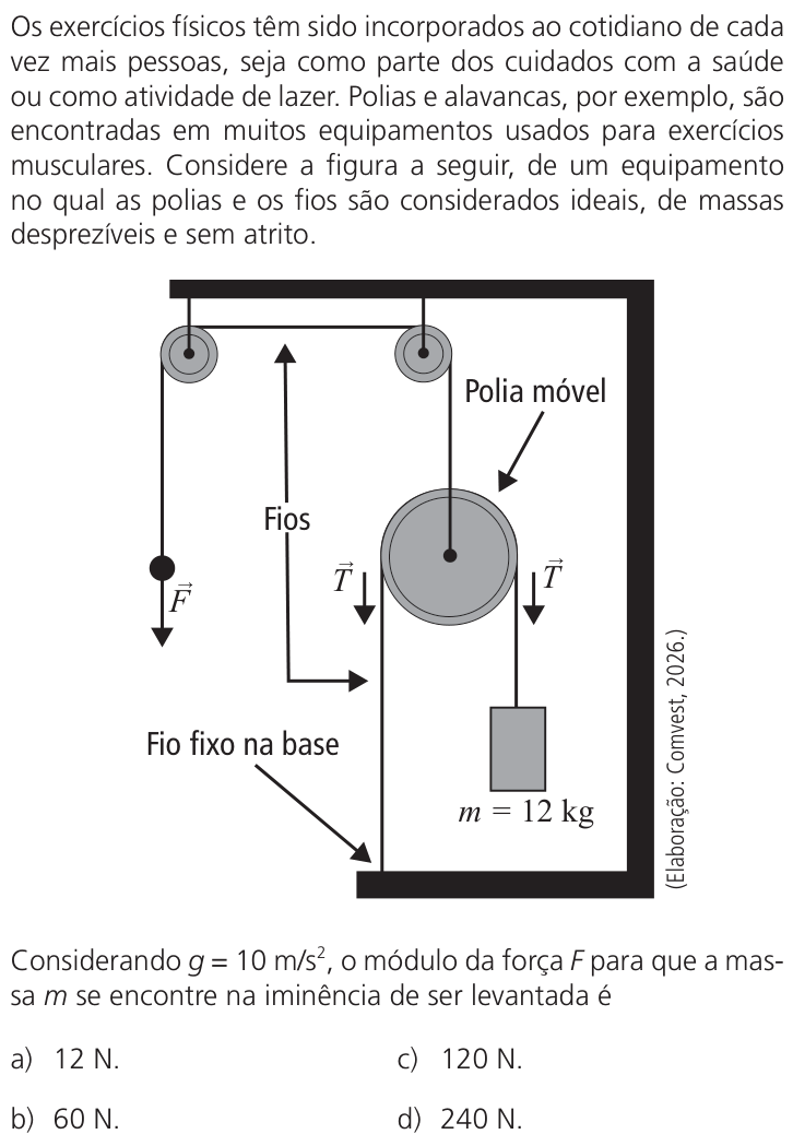
A figura representa um sistema com fios e polias ideais. Um dos fios tem uma extremidade fixa na base, passa pela polia móvel e sustenta a massa m na outra extremidade. Na iminência de levantamento, a tensão \vec{T} nesse fio equilibra o peso:
T = mg = 12 \times 10 = 120\,\mathrm{N}.
As duas partes desse fio puxam a polia móvel para baixo. Como a polia tem massa desprezível, a força resultante sobre ela é nula, de modo que a força vertical para cima que a sustenta deve valer 2T.
Essa força para cima é exercida pelo outro fio (que passa apenas por polias fixas). A tensão nesse fio é igual à força aplicada F, portanto
F = 2T = 240\,\mathrm{N}.
Resposta: D