Correção IME 2027 · Português e InglêsAcompanhe a resolução de cada questão da 2ª fase, ao vivoAcompanhar
IA ao vivo / IME 2027 · 2ª fase · Física

COMPARE OS RACIOCÍNIOS

Questão 2 (Física)

Questão discursiva: a banca não divulga gabarito oficial. ← 1 (Física) 3 (Física) →

A questão

Questão 2 (Física)

Resposta de referência

a) Em A: 200\,\text{kN}, vertical para cima; em B: 100\,\text{kN}, vertical para baixo; A_x=B_x=0. b) N_{CD}=N_{DE}=75\,\text{kN} (compressão); N_{CF}=N_{EF}=125\,\text{kN} (tração); N_{DF}=N_{AD}=200\,\text{kN} (compressão); N_{BE}=100\,\text{kN} (tração); N_{AE}=0. c) AE funciona como contraventamento, garantindo a rigidez e a estabilidade geométrica da treliça, podendo ser solicitada por cargas horizontais, embora tenha esforço nulo neste carregamento.

Segundo a resolução dos cursinhos Farias Brito e Poliedro. A banca não publica gabarito das questões discursivas.

Respostas das IAs

GPT-6 Astra

Respondeu · bate com a resposta de referência dos cursinhos

a) A: 200 kN, vertical para cima; B: 100 kN, vertical para baixo; b) CD: 75 kN (compressão), CF: 125 kN (tração), DF: 200 kN (compressão), AD: 200 kN (compressão), AE: 0, DE: 75 kN (compressão), BE: 100 kN (tração), EF: 125 kN (tração); c) AE é uma barra de contraventamento que garante a estabilidade geométrica da estrutura.

levou 38 s

Como pensou

a) Reações nos apoios A e B

Como a única barra ligada ao nó B é a barra vertical BE, o equilíbrio desse nó exige que a reação horizontal em B seja nula. Logo, pelo equilíbrio horizontal do guindaste,

B_x=0 \quad\Rightarrow\quad A_x=0.

Adotando o sentido anti-horário como positivo, o equilíbrio dos momentos em relação a A fornece:

\sum M_A=0 \quad\Rightarrow\quad 3P+3B_y=0.

Portanto,

B_y=-P=-100\ \text{kN}.

Pelo equilíbrio vertical:

A_y+B_y-P=0 \quad\Rightarrow\quad A_y=200\ \text{kN}.

Assim, as reações são verticais, sendo 200 kN para cima em A e 100 kN para baixo em B.

b) Esforços normais nas barras

Adotaremos N>0 para tração e N<0 para compressão. As barras inclinadas formam triângulos de lados 3, 4 e 5\ \text{m}; portanto, suas componentes horizontais e verticais têm fatores 3/5 e 4/5, respectivamente.

Nó C:

\sum F_y=0 \Rightarrow \frac45N_{CF}-100=0 \Rightarrow N_{CF}=125\ \text{kN}.
\sum F_x=0 \Rightarrow N_{CD}+\frac35N_{CF}=0 \Rightarrow N_{CD}=-75\ \text{kN}.

Nó F:

\sum F_x=0 \Rightarrow -\frac35N_{CF}+\frac35N_{EF}=0 \Rightarrow N_{EF}=125\ \text{kN}.
\sum F_y=0 \Rightarrow -N_{DF}-\frac45(N_{CF}+N_{EF})=0 \Rightarrow N_{DF}=-200\ \text{kN}.

Nó D:

\sum F_x=0 \Rightarrow -N_{CD}+N_{DE}=0 \Rightarrow N_{DE}=-75\ \text{kN}.
\sum F_y=0 \Rightarrow N_{DF}-N_{AD}=0 \Rightarrow N_{AD}=-200\ \text{kN}.

Nó A: como A_x=0 e AD é vertical,

\sum F_x=0 \Rightarrow \frac35N_{AE}=0 \Rightarrow N_{AE}=0.

Nó B:

\sum F_y=0 \Rightarrow N_{BE}+B_y=0 \Rightarrow N_{BE}=100\ \text{kN}.

Os resultados são:

Barra Módulo do esforço normal Natureza
CD 75\ \text{kN} Compressão
CF 125\ \text{kN} Tração
DF 200\ \text{kN} Compressão
AD 200\ \text{kN} Compressão
AE 0 Esforço nulo
DE 75\ \text{kN} Compressão
BE 100\ \text{kN} Tração
EF 125\ \text{kN} Tração

c) Função da barra AE

A barra AE funciona como contraventamento, formando o triângulo rígido ADE e garantindo a estabilidade geométrica do guindaste. Ela impede movimentos laterais por rotação das barras nas articulações.

Embora seu esforço seja nulo para o carregamento dado, sua retirada permitiria que a estrutura se comportasse como um mecanismo articulado. Sob outros carregamentos, como forças horizontais, AE pode apresentar esforço não nulo.

Resposta final: a) A: 200 kN, vertical para cima; B: 100 kN, vertical para baixo; b) CD: 75 kN (compressão), CF: 125 kN (tração), DF: 200 kN (compressão), AD: 200 kN (compressão), AE: 0, DE: 75 kN (compressão), BE: 100 kN (tração), EF: 125 kN (tração); c) AE é uma barra de contraventamento que garante a estabilidade geométrica da estrutura.

GPT-6.1 Sol

Respondeu · bate com a resposta de referência dos cursinhos

a) A: 200\,\text{kN} para cima; B: 100\,\text{kN} para baixo; reações horizontais nulas. b) CD = DE = 75\,\text{kN} (compressão); CF = EF = 125\,\text{kN} (tração); DF = AD = 200\,\text{kN} (compressão); BE = 100\,\text{kN} (tração); AE = 0. c) AE garante a estabilidade geométrica por contraventamento.

levou 37 s

Como pensou

Adotaremos os sentidos positivo horizontal para a direita e vertical para cima. Para os esforços nas barras, consideraremos tração positiva e compressão negativa.

As barras inclinadas têm projeções de 3\,\text{m} e 4\,\text{m}; portanto, seu comprimento é 5\,\text{m}, e os módulos das componentes de um esforço N são 3N/5 e 4N/5.

a) Reações em A e B

No nó B, a única barra incidente, BE, é vertical. Assim,

B_x=0.

Pelo equilíbrio horizontal da estrutura:

A_x+B_x=0\quad\Rightarrow\quad A_x=0.

Tomando momentos em relação a A, com sentido anti-horário positivo:

3P+3B_y=0 \quad\Rightarrow\quad B_y=-P=-100\,\text{kN}.

Pelo equilíbrio vertical:

A_y+B_y-P=0 \quad\Rightarrow\quad A_y=200\,\text{kN}.

Logo, as reações são

\boxed{R_A=200\,\text{kN},\ \text{vertical para cima}}

e

\boxed{R_B=100\,\text{kN},\ \text{vertical para baixo}}.

O apoio B deve, portanto, resistir ao levantamento da estrutura.

b) Esforços normais nas barras

Nó C

Do equilíbrio vertical:

\frac45N_{CF}-100=0 \quad\Rightarrow\quad \boxed{N_{CF}=125\,\text{kN}\ \text{(tração)}}.

Do equilíbrio horizontal:

N_{CD}+\frac35N_{CF}=0 \quad\Rightarrow\quad \boxed{N_{CD}=-75\,\text{kN}\ \text{(compressão)}}.

Nó F

Do equilíbrio horizontal:

-\frac35N_{CF}+\frac35N_{EF}=0 \quad\Rightarrow\quad \boxed{N_{EF}=125\,\text{kN}\ \text{(tração)}}.

Do equilíbrio vertical:

-\frac45N_{CF}-\frac45N_{EF}-N_{DF}=0,
\boxed{N_{DF}=-200\,\text{kN}\ \text{(compressão)}}.

Nó D

Do equilíbrio horizontal:

-N_{CD}+N_{DE}=0 \quad\Rightarrow\quad \boxed{N_{DE}=-75\,\text{kN}\ \text{(compressão)}}.

Do equilíbrio vertical:

N_{DF}-N_{AD}=0 \quad\Rightarrow\quad \boxed{N_{AD}=-200\,\text{kN}\ \text{(compressão)}}.

Nó B

Do equilíbrio vertical:

B_y+N_{BE}=0 \quad\Rightarrow\quad \boxed{N_{BE}=100\,\text{kN}\ \text{(tração)}}.

Nó A

Como A_x=0 e AD é vertical, o equilíbrio horizontal fornece:

A_x+\frac35N_{AE}=0 \quad\Rightarrow\quad \boxed{N_{AE}=0}.

Os resultados estão reunidos na tabela:

Barra Módulo do esforço normal Natureza
CD 75\,\text{kN} Compressão
CF 125\,\text{kN} Tração
DF 200\,\text{kN} Compressão
AD 200\,\text{kN} Compressão
AE 0 Esforço nulo
DE 75\,\text{kN} Compressão
BE 100\,\text{kN} Tração
EF 125\,\text{kN} Tração
c) Função da barra AE

A barra AE funciona como contraventamento, triangulando o quadrilátero ADEB e garantindo a estabilidade geométrica da estrutura.

Embora seu esforço seja nulo para o carregamento indicado, sua retirada permitiria um movimento lateral do conjunto, transformando-o em um mecanismo. Portanto, esforço nulo não significa que a barra seja dispensável.

Resposta final: a) A: 200\,\text{kN} para cima; B: 100\,\text{kN} para baixo; reações horizontais nulas. b) CD = DE = 75\,\text{kN} (compressão); CF = EF = 125\,\text{kN} (tração); DF = AD = 200\,\text{kN} (compressão); BE = 100\,\text{kN} (tração); AE = 0. c) AE garante a estabilidade geométrica por contraventamento.

GPT-6 Luna

Respondeu · diferente da resposta de referência dos cursinhos

a) R_A=150\,\text{kN} vertical para cima; R_B=50\,\text{kN} vertical para baixo; componentes horizontais nulas. b) CD: 75\,\text{kN} (compressão); CF: 125\,\text{kN} (tração); DF: 150\,\text{kN} (compressão); AD: 150\,\text{kN} (compressão); AE: 0; DE: 75\,\text{kN} (compressão); BE: 50\,\text{kN} (tração); EF: 25\sqrt{13}\,\text{kN} (tração). c) AE triangula e estabiliza a estrutura, embora não tenha esforço neste carregamento.

levou 48 s

Como pensou
**Analyzing truss statics** I need to solve the statics of a truss and start by parsing the coordinates of the nodes: A=(0,0), B=(6,0), D=(0,4), E=(6,4), F=(0,8), and C=(-3,4). The members are CD, CF, DF, AD, AE, DE, BE, and EF. At joint C, there’s a load P, with CD horizontal and CF sloping at 4/3. The supports at A and B are likely pinned, suggesting vertical reactions. The system seems statically indeterminate due to too many reactions for the available equations of equilibrium.**Calculating truss reactions** I'm working through the equations for a determinate truss, but it seems like we might have only three equations for overall equilibrium, suggesting some redundancy. If supports A and B are pinned, they're likely vertical only, giving me r=2. I’m considering how internal stresses affect the system, especially since there’s a vertical load without horizontal forces. Each joint offers reactions that could make the setup statically indeterminate. I'll analyze reactions at the joints based on that and see if I can solve it effectively.**Analyzing truss structure** I need to graph the truss with 8 members and 6 joints: C, D, F, A, E, and B. I want to find the reactions (r). According to the formula for planar determinate structures, m + r = 2j gives me 8 + r = 12, leading to r = 4. This means both supports A and B are likely pin supports. Even though there are only three global equilibrium equations, the additional joint equations provide further constraints, especially for determining horizontal reactions based on the geometry.**Analyzing panel structure** I'm breaking down the rectangular panel A-D-E-B and realizing I need to visualize the orientation of its elements: E-B being vertical, D-E horizontal, A-D vertical, and A-E as diagonal. This setup provides a triangular configuration for the quadrilateral. Joint A/D doesn't carry any load, but removing A-E could affect the mechanism. I should clarify how ties from A to E maintain the panel's rigidity and stability. The situation is interesting, as certain members can have zero forces under specific loading conditions without risking structural integrity.**Clarifying truss calculations** I'm working through a standard engineering diagram with a triangular support and a hatched base acting as a pin support. The reactions I'm calculating are vertical due to the structure, which makes sense, and internal forces are consistent. The geometry for force CF looks correct using C to F with the correct distances. I want to demonstrate reactions by possibly solving joints first and then applying global equilibrium to find Ay and By. I've deduced By as -50 kN and Ay as 150 kN, while horizontal forces are zero, which seems to fit.**Examining support reactions** I'm noting that the global moment is counterclockwise (CCW) and signifies positive. Downward forces on the left indeed cause a CCW which gives torque of +300. Therefore, By must pull downward to create clockwise motion. My sketch confirms support reactions are vertical, and since there are no horizontal loads, Ax plus Bx equals zero, so Bx will be zero. I can solve for reactions using external equilibrium, and with support A and B at the same level, I can see load C at x=-3 from A and a distance of 6.

Adoto como positivo o esforço normal de tração. As reações horizontais são R_{Ax} e R_{Bx}, e as verticais, R_{Ay} e R_{By}.

a) Reações nos apoios

Tomando momentos em torno de A, com sentido anti-horário positivo:

\sum M_A=0:\qquad 6R_{By}+100(3)=0

Logo, R_{By}=-50\,\text{kN}, isto é, a reação em B aponta para baixo. Pelo equilíbrio vertical,

R_{Ay}+R_{By}-100=0 \quad\Rightarrow\quad R_{Ay}=150\,\text{kN}.

No nó B, como a barra BE é vertical, o equilíbrio horizontal exige R_{Bx}=0. Assim, pelo equilíbrio horizontal do conjunto, R_{Ax}=0.

Portanto, a reação em A é 150\,\text{kN} para cima, e a reação em B é 50\,\text{kN} para baixo.

b) Esforços normais nas barras

No nó C, a barra CF tem direção com componentes proporcionais a 3 na horizontal e 4 na vertical. Assim,

\sum F_y=0:\qquad \frac45N_{CF}-100=0 \quad\Rightarrow\quad N_{CF}=125\,\text{kN},
\sum F_x=0:\qquad N_{CD}+\frac35N_{CF}=0 \quad\Rightarrow\quad N_{CD}=-75\,\text{kN}.

Logo, CF está tracionada e CD, comprimida.

No nó F,

\sum F_x=0:\qquad -\frac35(125)+\frac{3}{\sqrt{13}}N_{EF}=0 \quad\Rightarrow\quad N_{EF}=25\sqrt{13}\,\text{kN},
\sum F_y=0:\qquad -\frac45(125)-\frac{2}{\sqrt{13}}N_{EF}-N_{DF}=0 \quad\Rightarrow\quad N_{DF}=-150\,\text{kN}.

No nó D, usando os esforços já encontrados:

\sum F_x=0:\qquad 75+N_{DE}=0 \quad\Rightarrow\quad N_{DE}=-75\,\text{kN},
\sum F_y=0:\qquad -150-N_{AD}=0 \quad\Rightarrow\quad N_{AD}=-150\,\text{kN}.

No nó E, as componentes de N_{EF}=25\sqrt{13}\,\text{kN} são 75\,\text{kN} para a esquerda e 50\,\text{kN} para cima. Como N_{DE}=-75\,\text{kN}, a barra DE exerce 75\,\text{kN} para a direita no nó E. Portanto,

\sum F_x=0:\qquad -75+75-\frac{3}{\sqrt{13}}N_{AE}=0 \quad\Rightarrow\quad N_{AE}=0,
\sum F_y=0:\qquad 50-N_{BE}=0 \quad\Rightarrow\quad N_{BE}=50\,\text{kN}.

Assim:

Barra Esforço normal Estado
CD 75\,\text{kN} Compressão
CF 125\,\text{kN} Tração
DF 150\,\text{kN} Compressão
AD 150\,\text{kN} Compressão
AE 0 Barra sem esforço neste caso
DE 75\,\text{kN} Compressão
BE 50\,\text{kN} Tração
EF 25\sqrt{13}\,\text{kN} Tração

c) Função da barra AE

Embora AE seja uma barra sem esforço para este carregamento específico, ela triangula o painel inferior da estrutura e contribui para sua rigidez e estabilidade, impedindo deformações que poderiam ocorrer sem essa ligação. Em outras situações de carregamento, ela pode transmitir esforço normal.

Resposta final: a) R_A=150\,\text{kN} vertical para cima; R_B=50\,\text{kN} vertical para baixo; componentes horizontais nulas. b) CD: 75\,\text{kN} (compressão); CF: 125\,\text{kN} (tração); DF: 150\,\text{kN} (compressão); AD: 150\,\text{kN} (compressão); AE: 0; DE: 75\,\text{kN} (compressão); BE: 50\,\text{kN} (tração); EF: 25\sqrt{13}\,\text{kN} (tração). c) AE triangula e estabiliza a estrutura, embora não tenha esforço neste carregamento.

Claude Fable 5.1

Respondeu · bate com a resposta de referência dos cursinhos

a) R_A = 200 kN, vertical para cima; R_B = 100 kN, vertical para baixo; b) CD = 75 kN (compressão), CF = 125 kN (tração), DF = 200 kN (compressão), AD = 200 kN (compressão), AE = 0, DE = 75 kN (compressão), BE = 100 kN (tração), EF = 125 kN (tração); c) AE tem esforço nulo nesse carregamento; sua função é triangular o painel ADEB, garantindo rigidez/estabilidade da estrutura para outros carregamentos (horizontais ou em outras posições).

levou 32 s

Como pensou
I'm placing coordinates for the joints A through F and listing out the 8 members connecting them, checking that the truss has 6 joints to verify the structure is statically determinate. Working through the method of joints: starting at joint C with the 100 kN load, I find CF in tension at 125 kN and CD in compression at 75 kN. Moving to joint F, I solve for EF (125 kN tension) and DF (200 kN compression) using equilibrium. Now I'm moving to joint D, bringing in the force from CD along with DE, DF, and AD to continue solving the forces. Solving the horizontal and vertical equations at joint E gives F_AE = 0 and F_BE = 100 kN tension. Then checking joints A and B, the reactions come out to R_A = 200 kN upward and R_B = 100 kN downward, and the vertical equilibrium checks out at zero, so I'm now verifying moments about A to confirm consistency. As for why AE carries zero force under this particular loading, it's likely just a zero-force member for this case—its real purpose is to stabilize the structure against other loading conditions (horizontal loads, wind, asymmetric cases) and prevent the quadrilateral ADEB from behaving as a mechanism rather than a rigid frame.

Geometria: A=(0,0), B=(3,0), D=(0,4), C=(−3,4), E=(3,4), F=(0,8). As barras CF e EF têm comprimento 5 m (cos = 3/5, sen = 4/5); AE também (3,4,5).

Convenção: tração positiva (+), compressão negativa (−). Método dos nós.

Nó C (só CD e CF, carga P = 100 kN para baixo):

  • Vertical: (4/5)N_CF = 100 → N_CF = 125 kN (tração)
  • Horizontal: N_CD + (3/5)(125) = 0 → N_CD = −75 kN (compressão)

Nó F (CF, DF, EF):

  • Horizontal: −(3/5)(125) + (3/5)N_EF = 0 → N_EF = 125 kN (tração)
  • Vertical: −(4/5)(125) − (4/5)(125) − N_DF = 0 → N_DF = −200 kN (compressão)

Nó D (CD, DE, DF, AD):

  • Horizontal: 75 + N_DE = 0 → N_DE = −75 kN (compressão)
  • Vertical: −200 − N_AD = 0 → N_AD = −200 kN (compressão)

Nó E (DE, EF, BE, AE):

  • Horizontal: +75 (de DE comprimida) − (3/5)(125) − (3/5)N_AE = 0 → N_AE = 0
  • Vertical: (4/5)(125) − N_BE − (4/5)N_AE = 0 → N_BE = 100 kN (tração)

a) Reações

Nó A: a barra AD (comprimida) empurra A para baixo com 200 kN e AE não transmite força; AE=0 ⇒ não há componente horizontal. Logo R_A = 200 kN, vertical, para cima.

Nó B: a barra BE (tracionada) puxa B para cima com 100 kN ⇒ R_B = 100 kN, vertical, para baixo (o apoio B "segura" a estrutura para não tombar).

Verificação: ΣF_y = 200 − 100 − 100 = 0 ✓; ΣM_A = 100·3 − 100·3 = 0 ✓.

b) Esforços normais

  • CD: 75 kN, compressão
  • CF: 125 kN, tração
  • DF: 200 kN, compressão
  • AD: 200 kN, compressão
  • AE: 0 (barra de força nula)
  • DE: 75 kN, compressão
  • BE: 100 kN, tração
  • EF: 125 kN, tração

c) Função da barra AE

Para este carregamento, AE tem esforço nulo, mas ela não é inútil: o quadrilátero ADEB, sozinho, seria um mecanismo articulado (não triangulado). A diagonal AE triangula o painel, garantindo a rigidez geométrica/estabilidade da treliça, resistindo a esforços horizontais (vento, cargas inclinadas, frenagem da carga) e a outras posições de carga (por exemplo carga do lado de E), além de reduzir o comprimento de flambagem efetivo e conferir redundância/segurança à estrutura.

Resposta final: a) R_A = 200 kN, vertical para cima; R_B = 100 kN, vertical para baixo; b) CD = 75 kN (compressão), CF = 125 kN (tração), DF = 200 kN (compressão), AD = 200 kN (compressão), AE = 0, DE = 75 kN (compressão), BE = 100 kN (tração), EF = 125 kN (tração); c) AE tem esforço nulo nesse carregamento; sua função é triangular o painel ADEB, garantindo rigidez/estabilidade da estrutura para outros carregamentos (horizontais ou em outras posições).

Claude Opus 5.5

Respondeu · bate com a resposta de referência dos cursinhos

a) A: 200 kN vertical para cima; B: 100 kN vertical para baixo; reações horizontais nulas. b) CD = 75 kN (compressão); CF = 125 kN (tração); DF = 200 kN (compressão); AD = 200 kN (compressão); AE = 0; DE = 75 kN (compressão); BE = 100 kN (tração); EF = 125 kN (tração). c) AE tem esforço nulo nesse carregamento, mas triangula o painel ADEB, garantindo a estabilidade (sem ela a estrutura vira mecanismo) e resistindo a cargas laterais ou a outros carregamentos.

levou 30 s

Como pensou
I'm setting up coordinates for joints A through F, placing the 100 kN load at C, and confirming the truss is statically determinate with 8 members and 4 reactions across 6 joints. Now I'm working through the equilibrium equations at joint C, considering the forces along members CD and CF. Working through joint F gives tension in EF and compression in DF, then joint D yields matching compression in DE and AD. Moving to joint E, I find that AE carries zero force while BE comes out as 100 kN tension, and now I'm checking how that tension force at BE translates into the reaction at support B. Looking at joint A next, the compression in AD pushes straight down on A while AE contributes nothing, so the reaction there balances out at 200 up with no horizontal component. I verify everything with a vertical equilibrium check and a moment balance about A, confirming both reactions have zero horizontal component since the only connecting members are vertical. Now I'm moving on to classify AE as a zero-force member under this loading condition.

Adoto origem em A, com x para a direita e y para cima:
A(0,0), B(3,0), C(−3,4), D(0,4), E(3,4), F(0,8).
Esforço normal positivo indica tração. As barras inclinadas têm comprimento 5 m, com cos = 3/5 e sen = 4/5.

a) Reações

  • Momentos em relação a A: 100·3 + B_y·3 = 0, logo B_y = −100 kN. A reação em B aponta para baixo, o que significa que o apoio segura a estrutura e impede o tombamento.
  • Equilíbrio vertical: A_y + B_y − 100 = 0, logo A_y = 200 kN, para cima.
  • Horizontais: em B só chega a barra vertical BE, então B_x = 0. Daí A_x = 0.

b) Esforços normais (método dos nós)

Nó C:

  • Vertical: (4/5)N_CF − 100 = 0, logo N_CF = 125 kN.
  • Horizontal: N_CD + (3/5)N_CF = 0, logo N_CD = −75 kN.

Nó F:

  • Horizontal: −(3/5)·125 + (3/5)N_EF = 0, logo N_EF = 125 kN.
  • Vertical: −(4/5)·125 − (4/5)·125 − N_DF = 0, logo N_DF = −200 kN.

Nó D:

  • Horizontal: −N_CD + N_DE = 0, logo N_DE = −75 kN.
  • Vertical: N_DF − N_AD = 0, logo N_AD = −200 kN.

Nó E:

  • Horizontal: −N_DE − (3/5)·125 − (3/5)N_AE = 0, ou seja, 75 − 75 − 0,6·N_AE = 0, logo N_AE = 0.
  • Vertical: (4/5)·125 − (4/5)·0 − N_BE = 0, logo N_BE = 100 kN.

Verificação nos apoios:

  • Em A, a barra AD comprimida a 200 kN empurra o apoio para baixo, compatível com A_y = 200 kN para cima.
  • Em B, a barra BE tracionada a 100 kN puxa o apoio para cima, compatível com B_y = 100 kN para baixo.

Resultados:

  • CD: 75 kN, compressão
  • CF: 125 kN, tração
  • DF: 200 kN, compressão
  • AD: 200 kN, compressão
  • AE: 0
  • DE: 75 kN, compressão
  • BE: 100 kN, tração
  • EF: 125 kN, tração

c) Função da barra AE

Sob esse carregamento vertical, AE tem esforço nulo. Mesmo assim ela é indispensável por dois motivos:

  • Estabilidade: sem AE, o quadrilátero A‑D‑E‑B, articulado nos apoios A e B, forma um mecanismo de quatro barras. A estrutura ficaria hipostática, com 7 barras + 4 reações = 11 incógnitas para 12 equações, e poderia oscilar lateralmente. A diagonal AE triangula esse painel e garante a rigidez geométrica da treliça.
  • Outros carregamentos: AE passa a trabalhar quando há cargas horizontais (vento, frenagem, carga deslocada) ou qualquer outro caso de carga.

Resposta final: a) A: 200 kN vertical para cima; B: 100 kN vertical para baixo; reações horizontais nulas. b) CD = 75 kN (compressão); CF = 125 kN (tração); DF = 200 kN (compressão); AD = 200 kN (compressão); AE = 0; DE = 75 kN (compressão); BE = 100 kN (tração); EF = 125 kN (tração). c) AE tem esforço nulo nesse carregamento, mas triangula o painel ADEB, garantindo a estabilidade (sem ela a estrutura vira mecanismo) e resistindo a cargas laterais ou a outros carregamentos.

Claude Sonnet 5.5

Respondeu · bate com a resposta de referência dos cursinhos

a) A = 200 kN vertical para cima; B = 100 kN vertical para baixo (sem componentes horizontais); b) CD = 75 kN (compressão); CF = 125 kN (tração); DF = 200 kN (compressão); AD = 200 kN (compressão); AE = 0; DE = 75 kN (compressão); BE = 100 kN (tração); EF = 125 kN (tração); c) AE é uma barra de travamento: não carrega esforço neste caso, mas torna o painel ADEB rígido (isostático) e atua se a carga mudar.

levou 29 s

Como pensou
I'm setting up coordinates for joints A, B, C, D, E, F with a 100 kN load at C, and identifying the pinned supports at A and B along with the connecting bars CD, CF, DF, AD, AE, DE, BE, EF. I'm checking whether the structure is statically determinate by counting joints, equations, bars, and reaction forces. Now I'm solving for the reactions: taking moments about A gives By as 100 kN downward and Ay as 200 kN upward, and since bar BE is vertical, Bx and Ax must both be zero. At joint B, equilibrium shows BE carries 100 kN in tension. Moving to joint C, I'm resolving the forces along CD and CF (which runs at a 3-4-5 slope toward F), finding CF carries 125 kN in tension to balance the vertical load, with a corresponding 75 kN horizontal component pulling toward F. Working through joint F next, I'm balancing the horizontal and vertical components from CF, EF, and DF to find that EF carries 125 kN in tension, while DF comes out to 200 kN in compression based on the vertical equilibrium. Then checking joint E, resolving forces from EF, BE, AE, and DE, I find AE turns out to be zero and DE works out to 75 kN in compression based on the horizontal balance. Finally at joint D, summing the contributions from CD, DE, and DF, I need the remaining member AD to balance out the leftover vertical force. Though AE carries zero force under this particular loading, I realize it's still essential — it stabilizes the quadrilateral ADEB and prevents the structure from becoming a mechanism, since removing it would leave the frame with too few members relative to the reactions required for rigidity.

Eixos e dados: origem em A, x para a direita e y para cima. As coordenadas são A(0,0), B(3,0), D(0,4), E(3,4), C(–3,4) e F(0,8), em metros. A carga é P = 100 kN para baixo, em C.

a) Reações

Como BE é uma barra biarticulada e vertical, a reação em B só pode ser vertical. Logo B_x = 0.

Momentos em relação a A (anti-horário positivo):

+P·3 + B_y·3 = 0, então B_y = –100 kN.

Portanto B vale 100 kN, vertical, para baixo.

ΣF_x = 0 dá A_x = 0.

ΣF_y = 0 dá A_y + B_y = 100, então A_y = 200 kN.

Portanto A vale 200 kN, vertical, para cima.

b) Esforços normais (método dos nós)

  • Nó B: a reação de 100 kN para baixo é equilibrada pela barra BE puxando B para cima. Logo BE = 100 kN, tração.
  • Nó C: a componente vertical de CF equilibra P, então CF·(4/5) = 100 e CF = 125 kN, tração. A componente horizontal de CF puxa C para a direita com 75 kN, e CD equilibra isso empurrando C para a esquerda. Logo CD = 75 kN, compressão.
  • Nó F: na horizontal, EF·(3/5) = 125·(3/5), então EF = 125 kN, tração. Na vertical, as componentes de CF e EF puxam F para baixo com 100 + 100 = 200 kN, então DF = 200 kN, compressão.
  • Nó E: na vertical, EF puxa E para cima com 100 kN e BE puxa E para baixo com 100 kN. Então AE·(4/5) = 0 e AE = 0. Na horizontal, EF puxa E para a esquerda com 75 kN, então DE empurra E para a direita com 75 kN. Logo DE = 75 kN, compressão.
  • Nó D: na vertical, DF empurra D para baixo com 200 kN, então AD empurra D para cima com 200 kN. Logo AD = 200 kN, compressão. Na horizontal, CD e DE se anulam (75 kN cada, em sentidos opostos).
  • Verificação em A: AD comprimida empurra A para baixo com 200 kN, e A_y = 200 kN para cima equilibra. Está de acordo.
Barra Esforço (kN) Tipo
CD 75 compressão
CF 125 tração
DF 200 compressão
AD 200 compressão
AE 0 nula
DE 75 compressão
BE 100 tração
EF 125 tração

c) Função da barra AE

Para este carregamento, AE não recebe esforço. Ela é necessária para a estabilidade (rigidez) da estrutura. Sem AE, o quadrilátero articulado A‑D‑E‑B seria um mecanismo, pois teria 7 barras + 4 reações = 11 incógnitas para 12 equações dos nós, e a estrutura seria hipostática. AE triangulariza esse painel e torna a treliça isostática e indeformável. Ela também absorve esforços caso a carga mude de posição ou direção, por exemplo com cargas laterais ou de vento.

Resposta final: a) A = 200 kN vertical para cima; B = 100 kN vertical para baixo (sem componentes horizontais); b) CD = 75 kN (compressão); CF = 125 kN (tração); DF = 200 kN (compressão); AD = 200 kN (compressão); AE = 0; DE = 75 kN (compressão); BE = 100 kN (tração); EF = 125 kN (tração); c) AE é uma barra de travamento: não carrega esforço neste caso, mas torna o painel ADEB rígido (isostático) e atua se a carga mudar.

Grok 4.7

Respondeu · bate com a resposta de referência dos cursinhos

a) A: 200 kN vertical para cima; B: 100 kN vertical para baixo; b) CD: 75 kN compressão; CF: 125 kN tração; DF: 200 kN compressão; AD: 200 kN compressão; AE: 0; DE: 75 kN compressão; BE: 100 kN tração; EF: 125 kN tração; c) esforço nulo (garante a estabilidade da treliça)

levou 4 min 01 s

Como pensou
The problem involves a truss structure, specifically a crane in equilibrium with a force P applied at junction C. The applied force P is 100 kN downward. The truss geometry shows an 8 m height and 6 m horizontal span. I will calculate the reactions at A and B, determine the normal forces in bars CD, CF, DF, AD, AE, DE, BE, and EF, and explain the function of bar AE. I am mapping the truss coordinates. A is at (0,0) and B is at (3,0). C is 3 m left of A. D is directly above A. E is above B. Bars CF and DF are vertical. The remaining bars are horizontal CD and DE, vertical AD and BE, diagonal AE, and EF. Both supports appear to be pinned. The truss is likely statically determinate. The coordinates are now fixed: A at (0, 0), B at (3, 0), C at (-3, 4), D at (0, 4), E at (3, 4), and F at (0, 8). Both supports appear to be fixed pins, which would yield four external reactions for only three equilibrium equations. This suggests the structure may be externally indeterminate, unless one support is a roller. Counting the unknowns and equilibrium equations confirms the truss is statically determinate. Eight members plus four external reactions yield twelve unknowns, matching the twelve equilibrium equations from six joints. Global equilibrium alone cannot determine the four external reactions because only three equations exist. The method of joints or sections will be used instead to solve for the reactions and internal forces. I will use the method of joints to solve for the reactions. I will assume tension as positive and check signs. I am starting with joint C, which has three members: CD, CF, and the external load P. I am setting up the equilibrium equations at joint C. CD is horizontal and CF is diagonal with a slope of 3/5. I will assume tension in CD points rightward, so its force on the joint is positive in the x-direction. The equilibrium equations at joint C yield N_CF = 125 kN in tension and N_CD = -75 kN in compression. I am now moving to joint B, which appears to have only bar BE and the support reactions. Only bar BE is connected to joint B. The horizontal reaction at B must be zero, so the support reaction at B acts vertically along BE. I am now analyzing joint F. The force from bar CF is (-75, -100). I will write the equilibrium equations for joint F using the unknown tension in bar EF. The equilibrium equations at joint F yield N_EF = 125 kN in tension and N_DF = -200 kN in compression. The symmetry between CF and EF is unexpected because the external load is only on the left side. The symmetry at joint F is mathematically consistent. The horizontal force from bar CF is -75 kN, so bar EF must provide +75 kN to balance it. The vertical forces from both bars sum to -200 kN, which is exactly the compression in bar DF. I am now moving to joint D, where members CD, DF, AD, and DE meet. The force vectors at joint D are now clear. Bar CD pushes the joint rightward, and bar DF pushes it downward. The force from bar AD is still unknown. At joint D, the equilibrium equations yield N_DE = -75 kN in compression and N_AD = -200 kN in compression. I am now moving to joint E, where members DE, EF, AE, and BE meet. The force vectors at joint E are now defined. Bar DE pushes the joint rightward, bar EF pulls upward and leftward, and bars AE and BE act along the vertical and diagonal directions. The equilibrium equations for joint E will be written next. The equilibrium equations at joint E yield N_AE = 0 kN and N_BE = 100 kN in tension. Bar AE carries no force. I am now checking joint A to determine the external reactions. The vertical reaction at A is 200 kN. This conflicts with the requirement that the total upward reactions must equal the 100 kN downward load. I am now checking joint B to resolve this inconsistency. The vertical reaction at B is 100 kN downward. The total upward reactions now balance the 100 kN load. The remaining member forces are being listed. All six joints have been checked and the solution is internally consistent. The final member forces are AD compression 200, AE zero, DE compression 75, BE tension 100, and EF tension 125. I am now questioning whether a pinned support can actually provide a downward reaction. A pinned support can indeed provide a downward reaction when a member pulls it upward. The reactions are now fully specified: 200 kN upward at A and 100 kN downward at B, both acting vertically. I am also rechecking that AE carries zero force. I am verifying the reactions by calculating moments about point A. The downward load at C creates a clockwise moment of 300 kN·m. I am checking whether this moment is balanced by the support reactions. The moment check about point A confirms equilibrium. The clockwise torque from the load at C is 300 kN·m, and the reaction at B produces an equal and opposite torque of -300 kN·m. This validates the downward reaction at B. The moment equation about point A directly yields By = -100 kN and Ay = 200 kN. Horizontal reactions at B contribute no moment because their lever arm is zero. Horizontal reactions at A and B are indeterminate from global equilibrium alone. Opposite horizontal forces on the same line cancel both net force and moment, so any pair Ax = F and Bx = -F satisfies the equations. The joint analysis therefore uniquely determines Ax = Bx = 0. The joint method uniquely fixes the horizontal reactions at zero. This conflicts with the global equilibrium equations, which allow any pair of opposite horizontal forces. The member count formula is satisfied, so the solution should be unique. The apparent contradiction between the two methods needs resolution. The contradiction is resolved. If the horizontal reactions were nonzero, the internal forces would fail to satisfy equilibrium at one of the joints. Because every joint balances, the horizontal reactions must be zero. This confirms that global equilibrium and the joint method are fully consistent. I am rechecking joint D to verify the sign of the vertical force from member AD. The compression in AD pushes the joint upward with 200 kN, so I need to ensure this was correctly applied in the earlier equilibrium sum. I am now classifying the internal forces as tension or compression. Bar CD is 75 kN in compression. I am now considering a section cut through members AD, AE, and CF to verify the internal forces. The 200 kN compression in AD seems large because of the lever arm from the downward reaction at B. Bar AE carries no force under this load. It likely serves to prevent structural instability or to support other loading conditions. Removing bar AE leaves the truss with seven members, six joints, and four reactions. The count 7 + 4 = 11 is below the required twelve for rigidity, confirming the structure would become a mechanism without it. This validates that AE is essential for stability despite carrying zero force under this load. I am reconsidering the support types in the figure. The image might show fixed or roller supports rather than pinned ones, which would change the reaction directions and the need for bar AE. The horizontal forces at joint E cancel because the 75 kN compression in DE is balanced by the 75 kN horizontal component of the 125 kN tension in EF. This explains why bar AE carries no force. I am also considering whether support B might be a roller instead of a pin, which would change the reaction directions. Even if support B were a roller, the structure would remain unstable. The member count still yields only eleven constraints for twelve degrees of freedom, leaving an infinitesimal mechanism with zero energy modes that any small horizontal perturbation would amplify. The member count formula m+r=2j guarantees both static and kinematic determinacy. This means the structure is fully stable and cannot become a mechanism, even if support B were a roller. The figure shows both supports as identical triangles, so they are likely fixed pins. The reactions are vertical and the solution is correct. I am now drafting the final answer in Portuguese, beginning with a geometric analysis to establish angles and force components. The solution is being drafted in Portuguese. The 3-4-5 geometry gives sinθ = 4/5 and cosθ = 3/5 for the diagonal members. At joint C, the vertical equilibrium yields N_CF = 125 kN in tension, and the horizontal equilibrium yields N_CD = -75 kN in compression. At joint F, the horizontal equilibrium yields N_EF = 125 kN in tension. The vertical equilibrium yields N_DF = -200 kN in compression. At joint D, the horizontal equilibrium yields N_DE = -75 kN in compression. The final answer is now fully drafted in Portuguese. It lists the reactions at A and B, the internal forces in all eight members, and the explanation that bar AE carries zero force but is essential for structural stability. I am refining the explanation for bar AE. It may serve to brace compression members such as AD and DF, reducing their effective buckling length. The final explanation for bar AE is now settled. It carries no force under this load, but it is essential for structural stability and rigidity. The IME second-phase physics exam occasionally includes mechanics problems with trusses. The method of joints is advanced for high school level, but the institute's difficulty justifies such questions.

A estrutura é uma treliça plana isostática. As barras inclinadas (CF, EF e AE) formam triângulos retângulos 3-4-5; portanto, suas componentes horizontais e verticais valem, respectivamente, 3/5 e 4/5 do esforço normal. Os esforços são obtidos pelo método dos nós (convenção: tração positiva).

Nó C
\sum F_y=0: N_{CF}\cdot(4/5)=100\Rightarrow N_{CF}=125\,\text{kN} (tração).
\sum F_x=0: N_{CD}+125\cdot(3/5)=0\Rightarrow N_{CD}=-75\,\text{kN} (compressão).

Nó F
A barra CF aplica em F as componentes 75\,\text{kN} (para a esquerda) e 100\,\text{kN} (para baixo).
\sum F_x=0: N_{EF}\cdot(3/5)=75\Rightarrow N_{EF}=125\,\text{kN} (tração).
\sum F_y=0: as duas componentes verticais de 100\,\text{kN} exigem N_{DF}=-200\,\text{kN} (compressão).

Nó D
A barra CD (compressão) empurra D para a direita com 75\,\text{kN} e a barra DF (compressão) empurra D para baixo com 200\,\text{kN}.
\sum F_x=0: N_{DE}=-75\,\text{kN} (compressão).
\sum F_y=0: N_{AD}=-200\,\text{kN} (compressão).

Nó E
As componentes horizontais de DE e EF cancelam-se.
\sum F_x=0: N_{AE}=0.
\sum F_y=0: a componente vertical de EF (100\,\text{kN} para cima) exige N_{BE}=100\,\text{kN} (tração).

Nós A e B (reações)
Em A a barra AD (compressão) empurra o nó para baixo com 200\,\text{kN} e N_{AE}=0, logo a reação é 200\,\text{kN} vertical para cima (componente horizontal nula).
Em B a barra BE (tração) puxa o nó para cima com 100\,\text{kN}, logo a reação é 100\,\text{kN} vertical para baixo (componente horizontal nula).

O equilíbrio global confirma o resultado: \sum F_y=200-100-100=0 e o momento em relação a A também se anula (100\cdot3=100\cdot3).

Item (c)
O esforço em AE é identicamente nulo para o carregamento dado, de modo que a barra não participa da transmissão da força P. Sua presença é indispensável à estabilidade: sem ela teríamos m+r<2j e a treliça seria um mecanismo.

Resposta final: a) A: 200 kN vertical para cima; B: 100 kN vertical para baixo; b) CD: 75 kN compressão; CF: 125 kN tração; DF: 200 kN compressão; AD: 200 kN compressão; AE: 0; DE: 75 kN compressão; BE: 100 kN tração; EF: 125 kN tração; c) esforço nulo (garante a estabilidade da treliça)

DeepSeek V4.1 Flash

Respondeu · bate com a resposta de referência dos cursinhos

a) A: 200 kN vertical para cima; B: 100 kN vertical para baixo (componentes horizontais nulas); b) CD: 75 kN (compressão), CF: 125 kN (tração), DF: 200 kN (compressão), AD: 200 kN (compressão), AE: 0, DE: 75 kN (compressão), BE: 100 kN (tração), EF: 125 kN (tração); c) barra de contraventamento que garante estabilidade do painel inferior.

levou 1 min 21 s

Como pensou
We need answer solve statics truss. Need parse figure. Need provide in Portuguese. Need solve item by item. We need determine reactions at A and B, internal forces in bars CD, CF, DF, AD, AE, DE, BE, EF, and explain function of bar AE. Let's understand geometry. The structure: Points: A and B supports at bottom? Coordinates maybe: A at (0,0), B at (6,0)? Figure: horizontal distance from C to D? It says 3 m between C and A? Actually dimension bottom: left vertical dashed from C down to line through A, arrow 3 m; then between A and B arrow 3 m. So C is 3 m left of A. D likely above A? E 3 m right of A? B under E? Let's inspect. The figure: top F. Triangle F-C-E? There is vertical line F-D-A? D lies on horizontal line C-D-E. F connected to C and E. D is midpoint? C-D length 3, D-E length 3? The dimension shows total bottom from C to A 3 m, and A-B 3 m? Wait bottom dimension: from C (x=0?) to A? Arrow from C dashed vertically down to baseline then to A? Label 3 m. Then A to B label 3 m. Thus coordinates: C at x=0? A at x=3? B at x=6? D? D is vertically above A? There is vertical member A-D? Bar AD vertical? F-D? F above D. E? Horizontal C-D-E; D midpoint? Since C-D = 3, D-E=3, so E at x=6? Then E is directly above B? Yes vertical member BE from B to E? Bar BE vertical. A at x=3, B at x=6. E at x=6; D at x=3; F above D at same x? Top F connected to C and E; vertical FD. So structure: nodes: A (3,0), B (6,0), C (0,4?), D (3,4?), E (6,4?), F (3,8?)? Heights: C/D/E at 4 m above A/B? Figure right side arrow 4 m from E? There is dimension on right: from F to E (vertical distance 4 m?) Wait dimension line from F to E? Actually top arrow vertical: from F down to maybe horizontal through C/D/E? Label 4 m for top triangle height? Then another 4 m for rectangle/story? Let's examine: At right, vertical dimension line with arrows: top segment from F (top) down to horizontal line through C,D,E, labeled 4 m; lower segment from that horizontal line down to A/B supports labeled 4 m. So total height F to A is 8 m. Coordinates: supports at y=0? C,D,E at y=4? F at y=8? Thus yes: A=(3,0), B=(6,0), C=(0,4), D=(3,4), E=(6,4), F=(3,8). Check distances: CD=3, DE=3; AD vertical 4; BE vertical 4; FD vertical 4; CF inclined length sqrt(3^2+4^2)=5; FE same 5; AE? A to E: horizontal 3, vertical 4 => length 5 (bar AE diagonal? Figure shows diagonal from A to E indeed). So AE length=5. Triangle? Bar AE connects A(3,0) to E(6,4). It is diagonal. BE vertical. CE? Actually bar? Figure shows horizontal C-D-E; no CE horizontal? There is C-D, D-E. Bar AE diagonal. Bar BE vertical. Bars CD, CF, DF, AD, AE, DE, BE, EF. No bar AC? no bar CE? no bar AB? no bar BD? So truss with joints? It may be statically determinate? Let's count bars: given bars: CD, CF, DF, AD, AE, DE, BE, EF = 8 bars. Nodes: A,B,C,D,E,F = 6. 2j=12, reactions? supports: A and B are pinned? A support symbol triangle with hatching, B similarly. If both pinned, reactions 4 unknown -> total unknown 8+4=12, determinate? Actually internal forces m=8, reactions 4, equations 2j=12 -> total unknown 12, equations 2j=12, yes determinate? But maybe external load P at C. However if both supports pinned (no roller), each has two reaction components => 4 external unknowns + 8 internal =12, static equations 12. But some equations maybe singular? Need solve. However figure support A maybe pinned, B maybe roller? Symbols: Both have triangular support with ground hatching, maybe both are pinned? In Brazilian notation, triangle with hash could be articulated fixed? Usually a triangle with hash supporting node indicates pin support (reactions H and V). Could be both pinned. But maybe B is roller? Symbol same? Let's see: A and B each triangle with hash under node; no rollers. If both pinned, structure is externally indeterminate? But because truss maybe internally? Let's check count: If both supports pinned, external unknown 4. Equations equilibrium 3. Internal bars 8. Total unknown 12. Joint equations 12. Determinate only if 8 internal + 3 reactions = 11? Wait free body diagram of entire truss gives 3 equations with 4 reaction components + load: 4 unknowns -> not enough. But if include internal bars, count bars+reactions = 8+4=12, joints=6 => 2j=12. Static determinacy condition m + r = 2j => 8+4=12 yes. So determinate. But external reactions cannot be determined by overall equilibrium alone because 4 reactions, but internal equations help. Yes statically determinate truss (with two pinned supports? Usually if m+r=2j and stable, yes determinate, because r can be >3 if m < 2j-3? Here m=8 <9, so r=4 >3; total still determinate? Actually for plane truss, determinacy: m + r = 2j. If r=4, m=8, j=6 -> 12=12. It is determinate but external reactions not individually by global equilibrium; need solve all joints. However all nodes maybe with loads? Only load at C. Need solve. But wait if both supports are pins, there are horizontal reactions at A and B. But maybe there is a horizontal reaction? Load vertical P at C, no horizontal external load, so global sum horizontal = 0 => Ax + Bx =0. But need magnitudes. Joint equations will determine. Alternatively maybe one support is a roller? If B is roller, r=3, m=8, j=6 -> 2j=12, then m+r=11 <12 -> unstable? Actually missing one reaction -> mechanism? The bar AE perhaps acts as redundant if one support roller? But figure maybe A pinned, B roller? However support symbols both maybe "apoio articulado fixo"? Let's not assume; solve general with both pinned? Need maybe check if determinate. If both pinned, can solve joint equations; but might be overdetermined? No. Let's solve carefully. Coordinates: A=(3,0) (relative to C x=0) B=(6,0) C=(0,4) D=(3,4) E=(6,4) F=(3,8) Members: CD horizontal length 3 DE horizontal length 3 AD vertical length 4 BE vertical length 4 DF vertical length 4 CF diagonal slope from C(0,4) to F(3,8): dx=3, dy=4, length 5 EF diagonal from E(6,4) to F(3,8): dx=-3, dy=4, length 5 AE diagonal from A(3,0) to E(6,4): dx=3, dy=4, length 5. Load P at C downward: 100 kN. Node C has support? no, load. Supports A and B at base. Let's use method of joints. Need determine reactions at A and B. Let's denote: At A: Ax, Ay (positive right/up maybe) At B: Bx, By. Or use global equilibrium. All bars are two-force members? Yes if loads only at joints and no weight, each bar has axial force (tension or compression). At joints, forces along bars. We can solve node by node. Some zero-force? Let's identify. Node A: connected to D (vertical AD) and E (diagonal AE), plus support reactions Ax, Ay. No external load. Forces: AD, AE, reactions. That's 3 unknown? AD, AE, Ax, Ay? Wait node A unknowns: Ax, Ay, F_AD, F_AE =4 unknowns? But equilibrium equations 2 only. But maybe support reaction can be expressed? Actually node A has 4 unknowns (2 support + 2 bar forces) and 2 equations, underdetermined. But if solve other part, maybe. Node B: connected to E (vertical BE?) only? Actually B connected to E by bar BE. And support reactions Bx, By. At B: only one bar? Node B connected to E only (since no bar AB). If only one bar BE vertical and support reactions, node B equilibrium: sum Fx = Bx + bar? bar BE vertical no x component? Actually bar BE is vertical, so if bar force is vertical. Then horizontal reaction Bx = 0. Sum Fy: By + F_BE = 0. So Bx=0, By = -F_BE. Unknown relation. If support B pinned, horizontal reaction zero due to no horizontal bar. But is there any other bar? B-E only. So yes Bx=0. But node E also connected to B, D, F, A? Let's solve. Node B: two equations: Bx = 0, By + F_BE =0 (depending tension positive). So Bx=0. Good. Node E: connected bars DE (horizontal), BE (vertical down), AE (diagonal down-left), EF (diagonal up-left to F), maybe CE? no. At E, no external load. Four bars -> 4 unknown forces? But if we know some from other nodes. Let's define tension positive. Let's assign unit vectors from node to connected nodes: At C: connected D (horizontal right), F (diagonal up-right). Load P down. Also? C connected D and F only? no bar CF and CD. Node C equations: F_CD (right), F_CF (towards F) with unit (3,4)/5 = (0.6,0.8) from C to F (dx=3,dy=4). Load P = (0,-100). Equilibrium: Sum Fx: F_CD + (3/5) F_CF = 0? Wait if tension positive, force exerted by bar on node points away from node along bar: for CD at C, direction from C to D = (1,0), force = T_CD*(1,0). For CF from C to F = (3/5,4/5), force = T_CF*(3/5,4/5). Load (0,-P). Sum Fx = T_CD + (3/5)T_CF =0. Sum Fy = (4/5)T_CF - P =0. Thus T_CF = P/(4/5)= (5/4)P = 125 kN (tension). Then T_CD = - (3/5)*125 = -75 kN (i.e. compression? T negative means compression force on node opposite direction? Let's verify: T_CF tension =125 kN; its x component at C is 125*0.6=75 kN to right, y comp 100 kN up. To balance, horizontal component must be -75 kN, so T_CD must be -75 kN (compression), i.e. bar CD pushes node left? Force from CD on node C is -75*(1,0) = (-75,0) if T negative? Actually T_CD positive tension would pull node right; negative tension compression pushes node left. Yes compression. Good. Node D: connected to C (horizontal left), E (horizontal right), A (vertical down), F (vertical up). Need determine F_CD known: -75 kN (compression, force on D from bar CD? At D, bar CD direction from D to C is left; if tension positive, force on D is left. Since T_CD=-75, force on D? For negative (compression), force at D points away from joint? Let's use consistent: At node, bar force exerted by bar on node = T * unit vector from node to other end. If T negative, force opposite to that unit vector (towards other joint? Actually "tension" positive means bar pulls node toward other end? Hmm typical: If bar tension, it pulls node toward other end? Yes at node, force points toward the other end. So T positive force = T * (vector from node to other end)/L. If T negative, force points opposite (away from other end). Thus at D, T_CD=-75, unit from D to C = (-1,0); force from CD on D = -75*(-1,0) = (75,0)? Wait formula force = T * u, where u from node to other end. If T negative, force = -75*(-1,0)= (75,0), i.e. pushes D right. That seems due to compression: C-D compressed, at D it pushes toward right. Let's verify with global: CD compression: bar pushes C left (C to D? Actually at C bar compression pushes C left? At C, unit to D (1,0), T=-75 -> force = -75*(1,0)=(-75,0) left. Good. At D bar pushes D right, yes. So forces balance. At D: four bars: CD (left), DE (right), DA (down), DF (up). No external load. Vertical equilibrium: F_DF + F_DA? Need signs. Horizontal: F_DE + (force from CD at D) =0 -> F_DE + 75 =0? Wait force from CD on D = +75 in x. Force from DE on D: T_DE * unit from D to E (1,0) = T_DE. Sum Fx = T_DE + 75 =0 => T_DE = -75 kN (compression). Vertical equilibrium: force from DA (down? unit from D to A = (0,-1); force = T_DA*(0,-1) = (0,-T_DA)). Force from DF (up? unit from D to F = (0,1); force = T_DF*(0,1)). Sum Fy = T_DF - T_DA =0 => T_DF = T_DA. Not enough. Node F: connected C, D, E. Bars CF, DF, EF. Known T_CF=125 (tension), need T_DF maybe via vertical equilibrium at F? Node F equation: forces from CF, DF, EF. At F, unit from F to C = (-3,-4)/5 = (-0.6,-0.8); to D = (0,-1); to E = (3,-4)/5=(0.6,-0.8). Sum Fx = T_CF*(-0.6)+ T_EF*(0.6) + T_DF*0 =0? Wait DF vertical no x. So -0.6*125 + 0.6*T_EF =0 => T_EF =125 kN (tension). Sum Fy = T_CF*(-0.8) + T_DF*(-1) + T_EF*(-0.8) =0 => -0.8*125 - T_DF -0.8*125=0 => -100 - T_DF -100=0 => T_DF = -200 kN (compression). Thus T_DF = -200. Then from D vertical T_DA = T_DF = -200 kN (compression). So AD compression 200 kN? Wait T_DA = -200. Good. Node E: connected to D (left), B (down), F (up-left), A (down-left). Known T_DE=-75 (compression force at E: T_DE negative, unit from E to D = (-1,0); force = -75*(-1,0) = (75,0)? Actually at E, T_DE=-75 -> force = T * u(E->D=-1,0)= (-75)*(-1,0) = (75,0) right? Wait push to right. Let's carefully. T_DE = -75 (compression). At E, unit from E to D = (-1,0). Force from DE on E = T_DE * u = (-75)*(-1,0) = (75,0), i.e. right. This means bar DE pushes E right. At D earlier, force from DE on D = T_DE * u(D->E=(1,0)) = (-75)*(1,0)=(-75,0), pushes D left; opposite, fine. Known T_EF =125 (tension), force at E from EF: unit E->F = (-3,4)/5=(-0.6,0.8), force =125*(-0.6,0.8)=(-75,100) (left/up). Wait tension pulls E toward F (up-left), yes x left 75, y up 100. Unknown T_BE (vertical down to B), T_AE (diagonal to A). Need solve. At E, unit E->B = (0,-1), force = T_BE*(0,-1)=(0,-T_BE). Unit E->A = A(3,0)-E(6,4)=(-3,-4)/5=(-0.6,-0.8); force = T_AE*(-0.6,-0.8)=(-0.6 T_AE, -0.8 T_AE). Sum Fx: from DE +75? Wait force from DE on E is (75,0), plus EF (-75,0), plus AE (-0.6 T_AE), plus BE 0 =0. So 75 -75 -0.6 T_AE =0 => T_AE=0? That seems surprising. Let's check orientation: Node E equilibrium horizontal: Forces: DE: T_DE = -75, unit E->D = (-1,0), force = (-75)*(-1,0)+(75,0) right. EF: T_EF =125, unit E->F = (-0.6,0.8), force x = -75 (left). BE vertical no x. AE: unit E->A = (-0.6,-0.8), force x = -0.6 T_AE. Sum x = +75 -75 -0.6 T_AE =0 -> T_AE=0. Yes bar AE zero-force? But question asks explain function of bar AE? If zero force, maybe it is to provide stability? Wait maybe our coordinate assumption may be wrong? Let's not jump. Maybe geometry or support differs; or load direction? If T_AE=0, bar AE has no force. But question specifically asks "explique a função da barra AE" maybe because it's zero-force? But perhaps due to geometry, yes under this load AE is zero, but function is to stabilize the structure (prevent collapse under other loads) or ensure the lower triangle? Let's verify with vertical at E: Sum Fy = from DE 0 + EF 100 (up) + BE (-T_BE) + AE (-0.8 T_AE)=0 => 100 - T_BE -0.8*0 =0 => T_BE=100 kN (tension). So BE tension 100. Then at B, By = -T_BE = -100 kN? Reaction at B downward? Wait T_BE = 100 tension, at B force on node from BE: unit B->E = (0,1), force = T_BE*(0,1)=(0,100) upward (because tension pulls B up). Then equilibrium at B: By +100 =0 => By=-100 kN (downward). Bx=0. So B reaction: 100 kN downward? But support cannot pull down? A pin can exert downward force, yes it can resist up? Actually if bar pulls B upward, support must pull downward to keep equilibrium. So reaction at B is 100 kN downward. That's possible (tension anchor). But load P is downward, maybe structure tends to lift B? Let's check global vertical: Load downward 100 at C, supports A and B. Total downward load 100, so sum of support vertical reactions should be +100 upward? Wait external forces on truss: P=100 downward at C. Reactions at A and B. Sum Fy = Ay + By - 100 =0 => Ay + By =100. If By=-100, then Ay=200 upward. That seems possible. So B reaction downward 100, A upward 200? Let's solve A from global moments. But first verify with node A. Node A: connected D (up), E (diagonal up-right), supports Ax, Ay. Known T_AD? From D vertical equilibrium we got T_DA = T_DF = -200? Need recall at D vertical: T_DF = T_DA; T_DF = -200 from F. So T_AD? Let's define bar AD. At node D, T_AD? Wait bars are AD, DA same bar; tension same throughout T_AD. At D, T_DA we denoted force? Actually T_AD is tension in bar AD. At D, force from AD on D = T_AD * unit D->A = T_AD*(0,-1). At A, force from AD on A = T_AD * unit A->D = T_AD*(0,1). Our previous notation T_DA maybe same as T_AD? Let's be consistent: bar AD: T_AD. At D, force on D = T_AD * (0,-1) = (0,-T_AD). At A, force on A = T_AD * (0,1) = (0,T_AD). Earlier at D vertical equation: T_DF + force from AD y =0 => T_DF - T_AD =0 => T_DF = T_AD. Since T_DF = -200 => T_AD = -200 (compression). Good. At A, known T_AD = -200 (compression), force from AD on A = T_AD*(0,1) = (0,-200), i.e. downward 200? Wait negative * up = downward 200. So bar AD pushes A downward. That means if AD compression, at bottom A it pushes down. From A, yes. Unknown T_AE (we found 0), and support Ax, Ay. At A: connected E (up-right) and D (up). Sum Fx: force from AE if T_AE=0? Actually if T_AE=0, no force. Wait but equilibrium at A also includes Ax. Sum Fx = Ax + T_AE * unit A->E (3,4)/5? Unit A->E=(3,4)/5=(0.6,0.8). So x: Ax + 0.6*T_AE =0. If T_AE=0 => Ax=0. Sum Fy: Ay + T_AD (force from AD on A, unit A->D=(0,1)) + T_AE *0.8 =0 => Ay + (-200) + 0 =0 => Ay=200 kN upward. So reaction at A: 200 kN upward, no horizontal. Reaction at B: 100 kN downward? Wait if By=-100, direction downward. But is that physically possible? Supports both pinned; B can pull down. But maybe B support is a roller? If B were roller, vertical only; still could have downward reaction, but rollers usually cannot pull down unless tension? They can if held by pin? Typically roller can only push up; if reaction downward would require tie-down, not shown. Hmm maybe support symbols: At B, same triangular support with hatching; not roller. Pinned support can provide any direction, so downward okay. But perhaps in some conventions, a triangle with hash is fixed pin, both vertical/horizontal. So okay. However maybe load P at C downward could cause support B downward? Let's test by global moment about A: P at x=0? C at x=0? Wait coordinate C=(0,4), A=(3,0), B=(6,0). Load P at C downward 100 at x=0, y=4. Moment about A: force P has x=-3 relative A, y=4; moment = r x F = (-3,4) x (0,-100)= (-3)*(-100) - (4*0)=300 kN·m counterclockwise? Actually cross product r_x F_y - r_y F_x = (-3)*(-100)-4*0 = 300 (ccw? positive z). Reaction at B vertical By at x=6 relative A: r=(3,0), F=(0,By); moment = 3*By (positive if By up? formula r_x F_y =3*By). Reaction at A no moment. Sum moments about A =0: 300 + 3*By =0 => By = -100 kN. Yes B downward 100. Then Ay=200 upward. Good. Ax + Bx =0; from B no horizontal maybe Bx=0, so Ax=0. Good. So reactions: A = 200 kN upward (vertical), B = 100 kN downward (vertical) perhaps. But question "módulo, direção e sentido em A e B"; if B downward, direction vertical, sentido para baixo. Need include horizontal components zero. But wait is the structure stable if B reaction downward? It means structure is anchored at B; yes. Now item b: determine internal normal forces in bars CD, CF, DF, AD, AE, DE, BE, EF, indicate tension/compression. Based on above: CD: -75 kN (compression) CF: +125 kN (tension) DF: -200 kN (compression) [from F y: T_DF=-200; but bar DF vertical between D and F; at F force from DF? Let's check node F vertical equilibrium: T_CF=125, T_EF=125, T_DF? At F, unit F->D=(0,-1), force = T_DF*(0,-1)=(0,-T_DF). Sum Fy = -100 - T_DF -100 =0 => -T_DF -200=0 -> T_DF=-200. Yes compression.] AD: T_AD = T_DF? Need calculate via node D vertical? At D: DF force y = T_DF*(0,1)=(0,-200)? Wait unit D->F=(0,1); T_DF=-200 => force = (0,-200) downward? Wait if T_DF negative compression, force on D is -200 * up = down. Yes bar DF pushes D downward? Hmm because compression at F? Let's recompute to avoid sign errors. Let's use method of joints systematically with positive tension. I'll denote T_ij force in bar ij (tension positive). For each node, sum of forces from bars + external =0, using unit vectors from node to other. Node C: Bars: CD (C->D unit (1,0)); CF (C->F unit (0.6,0.8)); external P=(0,-100). Equations: xC: T_CD + 0.6 T_CF =0 yC: 0.8 T_CF -100=0 => T_CF=125. Then T_CD = -0.6*125 = -75. So CF tension 125, CD compression 75 (abs 75). Node D: Bars: DC (D->C unit (-1,0)); DE (D->E unit (1,0)); DA (D->A unit (0,-1)); DF (D->F unit (0,1)). External 0. Equations: x: T_DC*(-1) + T_DE*(1) + T_DA*0 + T_DF*0 =0? Wait T_DC same bar CD; use T_CD = -75. Force from CD on D = T_CD * unit D->C = (-75)*(-1,0) = (75,0). Formula: T_CD*u_DC. So x equation: T_CD*(-1) + T_DE*(1)=0 => -T_CD + T_DE =0 => T_DE = T_CD = -75. Yes. y: T_DA*(-1) + T_DF*(1)=0 => -T_DA + T_DF=0 => T_DF = T_DA. Need more info. Node F: Bars: FC (F->C unit (-0.6,-0.8)); FD (F->D unit (0,-1)); FE (F->E unit (0.6,-0.8)). External 0. Equations: x: T_CF*(-0.6) + T_EF*(0.6) + T_DF*0 =0 -> T_EF = T_CF =125. y: T_CF*(-0.8) + T_DF*(-1) + T_EF*(-0.8) =0 -> -0.8*125 - T_DF -0.8*125=0 -> -100 - T_DF -100=0 -> T_DF = -200. So compression 200. Then T_DA = T_DF = -200 (from D y). So AD compression 200. Node E: Bars: ED (E->D unit (-1,0)); EB (E->B unit (0,-1)); EF (E->F unit (-0.6,0.8)); EA (E->A unit (-0.6,-0.8)). External 0. Known T_DE = -75 (same bar DE), T_EF=125, unknowns T_BE, T_AE. Equations: x: T_DE*(-1) + T_EF*(-0.6) + T_EA*(-0.6) + T_BE*0 =0? Wait EB vertical no x. So (-1)*T_DE + (-0.6)*T_EF + (-0.6)*T_EA =0. Plug T_DE = -75, T_EF =125: -(-75) + (-0.6)(125) + (-0.6) T_EA = 75 -75 -0.6 T_EA =0 -> T_EA=0. y: T_DE*0 + T_EF*(0.8) + T_EA*(-0.8) + T_BE*(-1) =0 -> 0 + 0.8*125 + (-0.8)*0 - T_BE =0 -> 100 - T_BE=0 -> T_BE=100 kN tension. So AE zero. Node A: Bars: AD (A->D unit (0,1)); AE (A->E unit (0.6,0.8)); support Ax, Ay. External maybe no. Equations: x: T_AD*0 + T_AE*(0.6) + Ax =0 -> 0 + 0 + Ax=0 -> Ax=0. y: T_AD*(1) + T_AE*(0.8) + Ay =0 -> T_AD + Ay=0. T_AD = -200, so -200 + Ay=0 => Ay=200 kN upward. Good. Reaction A: 200 kN vertical upward (sentido para cima), horizontal zero. Since Ax=0, no horizontal component. Node B: Bars: BE (B->E unit (0,1)); support Bx, By. External no. Equations: x: T_BE*0 + Bx=0 -> Bx=0. y: T_BE*(1) + By =0 -> By = -T_BE = -100 kN. So By=100 kN downward. Reaction B: 100 kN vertical downward. Thus internal forces: CD: -75 kN => 75 kN compression CF: +125 kN => 125 kN tension DF: -200 kN => 200 kN compression AD: -200 kN => 200 kN compression (same as DF? Wait AD and DF are collinear vertical; yes both 200 compression? Actually bar DF and AD both vertical in same line? D between F and A; D connected to F above and A below; both compression. Since T_DF = T_AD = -200, yes both compression 200 kN. The load at C has no vertical? It creates compression in both? Let's reason: The force from top vertical bar gives downward on D and upward at F? T_DF=-200 compression means bar DF pushes D downward? Let's see at D, unit D->F=(0,1), force = T_DF*(0,1)=(-200)*(0,1)=(0,-200) downward. At F, unit F->D=(0,-1), force = T_DF*(0,-1)=(0,200) upward? Wait -200 * (0,-1) = (0,200) upward; so bar pushes F upward? But at F vertical loads from CF and EF are downward? Wait earlier at F equations: CF and EF vertical components: At F, bars CF and EF both unit have y component -0.8? Actually F->C =(-0.6,-0.8), T=125 => force y = -100 (down); F->E=(0.6,-0.8), T=125 => force y = -100 (down). Total downward from CF and EF =200. To balance, DF must pull F upward? If T_DF=-200, force at F from DF = T_DF*(F->D unit (0,-1)) = (-200)*(0,-1)=(0,200) upward. Yes DF compression pushes F up. At D, DF force down, combined with AD? At D, AD force down? T_AD=-200, unit D->A=(0,-1): force = (-200)*(0,-1)=(0,200) upward? Wait let's check: At D, unit D->A = (0,-1); T_AD=-200 => force = (-200)*(0,-1)= (0,200) upward. Wait then vertical at D: force from DF downward 200 + force from AD upward 200 =0. Good. At A, AD force = T_AD * A->D=(0,1) = -200*(0,1)=(0,-200) downward. So at A bar AD pushes down 200, support Ay up 200. Good. So both AD and DF compression? At AD, bar is compressed: ends push outward? At A force down, at D force up? Wait if compression, bar should push outward away from center: D force up? Hmm center of bar between A and D, compression would push D upward (away from A) and push A downward (away from D). Yes matches: D force upward, A force downward. So AD compression 200. DF compression: at D force downward? Compression would push D downward (away from F) and F upward (away from D). So yes. DE: -75 kN => 75 compression. BE: +100 kN => 100 tension. AE: 0 kN => zero force. EF: +125 kN => 125 tension. CF: 125 tension. CD: 75 compression. Need verify all bar forces satisfy global equilibrium? Sum vertical at D etc. Let's maybe present. But wait question asks "determine os esforços normais nas barras da estrutura (CD, CF, DF, AD, AE, DE, BE e EF), discriminando também se são de tração ou compressão". We should list all 8 bars: CD: compressão 75 kN CF: tração 125 kN DF: compressão 200 kN AD: compressão 200 kN AE: 0 (ou esforço nulo) DE: compressão 75 kN BE: tração 100 kN EF: tração 125 kN Need check if AE truly zero? Let's verify via other node maybe if no inconsistency: Node E solved using T_EF and T_DE. Check if T_AE=0, then E equilibrium vertical: T_EF vertical comp = 125*0.8 =100 up? Wait at E unit E->F = (-0.6,0.8) -> force y = +100 (up). T_DE force y=0. T_BE =100 tension, unit E->B=(0,-1), force = 100*(0,-1)=(0,-100) down. Sum y = 100 -100 =0. Good. Horizontal: T_DE compression force? T_DE=-75, unit E->D=(-1,0), force x=75 right. T_EF horizontal =125*(-0.6)=-75 left. Sum =0. Good. Node A: T_AD = -200, unit A->D=(0,1), force = (0,-200) down; support Ay = +200 up; T_AE? zero. Good. Node B: T_BE=100 tension, unit B->E=(0,1), force = (0,100) up; support By = -100 down; sum=0. Good. Node D: T_CD=-75, unit D->C=(-1,0), force=(75,0) right. T_DE=-75, unit D->E=(1,0), force=(-75,0) left. T_AD=-200, unit D->A=(0,-1), force=(0,200) up? Wait we computed force = (-200)*(0,-1)=(0,200) upward. T_DF=-200, unit D->F=(0,1), force=(0,-200) downward. Sum x 0, y 0. Good. Node F: T_DF=-200, unit F->D=(0,-1), force=(0,200) up. T_CF=125, unit F->C=(-0.6,-0.8), force = (-75,-100) (left/down). T_EF=125, unit F->E=(0.6,-0.8), force=(75,-100) right/down. Sum x 0, y 200-100-100=0. Good. Node C: T_CF=125, force C->F=(75,100) (up/right); T_CD=-75, force C->D=(-75,0); load (0,-100): sum 0. Good. All equilibrium satisfied. But wait is load P vertical downward at C; yes. Now item c: Explain function of bar AE. If its normal force is zero, its function likely structural stability, not load-carrying under this load; maybe prevents sway of the lower rectangle? Actually structure lower part is A-D-E-B? Wait bar AE diagonal in the lower rectangular bay? Actually rectangle A-D-E-B? There is bar AD vertical, DE horizontal, EB vertical, and bar AE diagonal. Without AE, would the lower part be kinematic? Let's analyze: The bars CD, DE, BE, AD, AB? There is no AB. Supports A and B fixed. The frame: left support A, right support B. Bars AD, DE, BE, and maybe AE. Without AE, can the lower part carry? There is no bar AB; but A and B fixed. The structure might be unstable? Let's check. The truss with all bars except AE: Nodes A and B fixed, bars AD, DE, BE, and upper part. Is it rigid? It might be a mechanism? Need explain AE provides stability to the rectangular panel under asymmetric loads; though zero under this symmetric? Actually load at C is symmetric? The geometry symmetric? Coordinates: A at 3, B at 6, C at 0. Load at C left of A, not symmetric. But AE zero due to load path? Let's test if removing AE makes horizontal equilibrium at E impossible? Node E without AE: bars DE, BE, EF, plus load? At E no external; equations: x -T_DE -0.6T_EF =0, y 0.8T_EF - T_BE =0. We solved T_DE=-75, T_EF=125, T_BE=100. This is possible, no AE. So AE is redundant for this load? But wait if load P at C downward, maybe AE carries zero; but if horizontal load or load at other nodes, it may carry. It likely prevents the rectangular bay A-D-E-B from distorting into a parallelogram; it braces the frame. The question asks "explique a função da barra AE." Could say: A barra AE é uma diagonal de contraventamento (travamento) da região inferior, impedindo a perda de forma/estabilidade do quadro ADEB. Embora, para o carregamento dado, seu esforço normal seja nulo, ela é necessária para garantir a rigidez e a estabilidade global, evitando mecanismo/colapso por deslocamento lateral. Maybe mention "barra de contraventamento". Need ensure if AE zero, maybe they expect "é uma barra inativa para esse carregamento, mas sua função é estabilizar a estrutura, evitando que os nós A,D,E,B formem um mecanismo (retângulo articulado) sob cargas não simétricas ou ações horizontais." That's likely. Need also maybe discuss "despreze os pesos das barras" so no self-weight. All bar forces are axial. Need maybe present reaction directions: Reaction at A: vertical upward, 200 kN; horizontal zero. Reaction at B: vertical downward, 100 kN; horizontal zero. But question: "determine as reações (módulo, direção e sentido) em A e B". We might need include direction/sentido: Em A: 200 kN vertical, sentido para cima; Em B: 100 kN vertical, sentido para baixo. But should we question whether B support can be downward? In Portuguese, "direção" = vertical; "sentido" = para baixo. Note: If a support can only react upward, then structure would be unstable under this load? But because truss is anchored? Hmm maybe the support at B might be a roller and thus only upward? Let's revisit support symbols and possibility. Looking at figure: A and B have equal triangular support with ground hatching; in many Brazilian textbooks, a triangle with hatching under vertex is "apoio articulado fixo" (pinned), not roller. A roller would be triangle with small circles under. So likely both pinned. But if B pinned, downward reaction means it pulls the structure down; okay. However, sometimes for truss, "A" may be a pinned support and "B" a roller? The symbols might be same because both are supports with a pin? In IME, they might use "apoio simples" (roller) maybe triangle with line? The image: The support at A and B both have triangle with hatching. Could be "apoio móvel" maybe triangle with rollers? Hard to see. The fact B reaction downward from global moment indicates if B were roller (only upward), equilibrium impossible: global moment about A gave By=-100 downward; a roller can only upward unless there is a tie-down. So to maintain equilibrium with load at C, B must be able to pull down. Thus either B is pinned or there is a holding-down force. If they intended roller, the structure would not be in equilibrium? Let's check: If B roller upward only, By>=0, moment about A: 300 +3 By =0 -> By=-100, impossible. So cannot be roller. Therefore B must be pinned/articulated fixed. So downward reaction is physical. Let's verify entire free body: Load 100 down at x=0, A reaction 200 up at x=3, B reaction 100 down at x=6. Sum vertical: -100 +200 -100=0. Moment about B: P at x=0 relative B x=-6: moment = (-6)*(-100) -? r=(-6,4), F=(0,-100): r_x F_y - r_y F_x = (-6)*(-100) -4*0 =600 ccw. A reaction at x=3 relative B x=-3: F=(0,200): moment = (-3)*200 = -600 cw. Sum=0. Good. Now, if B is pinned, there may be horizontal reaction Bx. But global horizontal equilibrium: Ax+Bx=0. Node A gave Ax=0 due to zero AE, so Bx=0. So okay. Need maybe solve reactions using global equilibrium and moment; but in written solution, show. Let's see if there is any other interpretation of coordinates: Maybe D is at midpoint horizontally, but C-D = 3 and D-E =3, yes. The bottom dimension: from C dashed to A is 3 m, and A-B is 3 m. So C at x=0, A at x=3, B at x=6. Good. Actually if C-D =3 and D-E=3, E at x=6; yes. But wait the lower horizontal dimension line "3 m" from C to A: It is between vertical lines through C and A (dashed). Then A-B "3 m". So yes. Now need maybe "determine os esforços normais" maybe they want all in kN, with signs? In Portuguese, "tração" positive, "compressão" negative maybe; but they ask "discriminando também se são de tração ou compressão". So we can list each bar with magnitude and type. Let's plan final response: - Introduce geometry/coordinates maybe. - Item a: reactions. Use global equilibrium maybe: * Sum moments about A: P * 3? Wait P at C x=0, A x=3, so horizontal distance 3 m; P downward at horizontal distance 3 m from A? Let's compute moment: P at C (x=0) vertical downward; line of action vertical through x=0; perpendicular distance to A (x=3) is 3 m. Moment = P*3 = 300 kN·m clockwise? Let's define sign. We want determine By. If B at x=6, distance from A to B horizontal 3 m. By upward would create counterclockwise moment about A? Actually force upward at right of A tends to rotate counterclockwise? Let's check: A at (3,0), B at (6,0), By upward. Cross r=(3,0), F=(0,By): moment =3*By. Positive if By up. P downward at C (x=0) => r=(-3,4), F=(0,-100): moment = (-3)*(-100) - 4*0 =300 positive (counterclockwise? Let's check coordinate: y up, x right. Force down at left of A: on left, downward force tends to rotate counterclockwise? Imagine pivot A, force down at left: rotation counterclockwise? Pull left side down => clockwise? Wait at left of pivot, downward force causes clockwise if pivot is right? Let's physically: Pivot A at x=3. Force at x=0 downward: line of action is to left of pivot; downward force on left tends to rotate the left side down, which is counterclockwise? Actually if pivot at right, pushing left side down means rotation? Visual: left end down, right pivot, that's counterclockwise? The left side goes down, so the bar rotates clockwise? Hmm coordinate: vector r=(-3,4) from A; force down (0,-100). Cross r_x F_y = (-3)*(-100)=300; by right-hand rule positive z means counterclockwise. Let's test: A at origin, point at (-3,0), force downward. Cross (-3,0) x (0,-1) = (-3)*(-1) -0 =3 positive (z out) means counterclockwise? If point left, force down, yes it tends to rotate counterclockwise? Imagine arrow at left pointing down: from pivot to arrow left; force down; tangential component? Actually if pivot at origin, force at (-3,0) downward: torque = 3? Point left, force down: rotates counterclockwise? Imagine looking: left end moves down, so about pivot, the angle from negative x axis goes toward negative y; that is counterclockwise (from 180° to 270°?) Wait angle from positive x: left =180°, down =270°, so angle increases, counterclockwise. Yes positive. So P creates counterclockwise moment +300. By upward at x=6 (right of pivot), force up: point at (3,0), force up, torque = 3*By (r positive, F positive) = positive? Right end up rotates counterclockwise? Right end up from pivot: angle from positive x 0° to positive y 90°, counterclockwise. Yes positive. So equation 300 +3 By =0 => By=-100 (clockwise). Good. So By downward 100. * Sum vertical: Ay + By -100=0 => Ay=200 upward. * Sum horizontal: Ax + Bx=0; from joint equilibrium or symmetry? We can state by joint B, Bx=0, hence Ax=0. Or global moment and horizontal maybe not enough; but global horizontal only says Ax=-Bx. Need use zero bar? Alternatively node B has no horizontal bar except support, so Bx=0; hence Ax=0. But if presenting item a before internal, can derive from node B: no horizontal force, so Bx=0. Or use global moment? not. - Item b: perhaps solve using method of joints. Need show development. Because final answer oververbosity desired 5; can present moderately detailed. Since question wants development, include equations for nodes maybe. Let's craft final response in Portuguese: "Adotarei tração positiva; unidades kN." Maybe start with geometry: Coordenadas (m): A=(3,0), B=(6,0), C=(0,4), D=(3,4), E=(6,4), F=(3,8). Comprimentos das barras inclinadas CF, EF e AE = 5 m; CD=DE=AD=BE=DF=4? Wait AD/BE/DF vertical =4 m, CD/DE horizontal =3 m. Actually CD=3, DE=3, AD=4, BE=4, DF=4. CF=EF=AE=5. Good. Need include. Then item a: - "Reações: Por equilíbrio global, momento em A: ΣM_A = 0: P*3 + By*3 =0? Wait P at x=0 relative A distance 3 on left; if using scalar with clockwise positive: P*3 - By*3? Let's define sign carefully in text: Considere momentos positivos no sentido anti-horário. A força P, de 100 kN para baixo, dista 3 m de A e produz momento +300 kN·m (pois tende a girar a estrutura no sentido anti-horário em torno de A). A reação By, em B, dista 3 m de A e, se for para cima, produz momento +3 By. Então 300 +3 By =0 => By=-100 kN (portanto, para baixo). Depois ΣFy= Ay+By-100=0 => Ay=200 kN. Ainda, como em B não há barra horizontal, Bx=0; por ΣFx=0, Ax=0. Logo reações: A = 200 kN vertical para cima; B = 100 kN vertical para baixo (ambas sem componente horizontal)." Need check moment sign: Actually if P produces +300? I earlier said P at left downward creates positive (counterclockwise). But if By upward also positive; then equation 300 + 3By =0 => By=-100. Yes consistent. But in scalar description, "P dista 3 m de A" horizontally; P downward at left of A. If positive anti-horário, yes P +300. By upward positive moment; so equation 300 +3By=0. Good. But if someone might interpret P clockwise? Let's maybe use torques: "P, para baixo à esquerda de A, tende a girar em torno de A no sentido anti-horário" yes. - Then item b: "Para os esforços normais, uso o método dos nós. Considerando tração positiva e as forças exercidas pelas barras nos nós com sentido para fora do nó (quando T>0)." Then present node C: Node C: ΣFx: T_CD + 0.6 T_CF =0 ΣFy: 0.8 T_CF - 100 =0 => T_CF = 125 kN (tração), T_CD = -75 kN (compressão). Node F: ΣFx: -0.6 T_CF +0.6 T_EF =0 => T_EF= T_CF=125 kN (tração). ΣFy: -0.8 T_CF - T_DF -0.8 T_EF =0 => -100 -T_DF -100=0 => T_DF = -200 kN (compressão). Node D: ΣFx: -T_CD + T_DE =0 => T_DE = T_CD = -75 kN (compressão). ΣFy: -T_AD + T_DF =0? Wait earlier at D y: -T_AD + T_DF =0? Let's verify: At D, force from AD on D = T_AD * unit D->A = T_AD*(0,-1) = (0,-T_AD). Force from DF = T_DF*(0,1) = (0,T_DF). Sum y = -T_AD + T_DF =0 => T_AD = T_DF. So T_AD = -200 kN (compressão). In text, if I write "ΣFy: -T_AD + T_DF =0 => T_AD=T_DF" okay. Node E: ΣFx: -T_DE -0.6 T_EF -0.6 T_AE =0. But T_DE=-75, T_EF=125: -(-75) -75 -0.6T_AE =0 => 0.6T_AE=0 => T_AE=0. ΣFy: 0.8 T_EF -0.8 T_AE - T_BE =0 => 100 -0 -T_BE=0 => T_BE=100 kN (tração). Node B: ΣFx: Bx=0; ΣFy: T_BE + By=0 (but if force from BE on B upward? At B, T_BE tension force upward; so T_BE + By=0 => By=-100, consistent). We can say "confirma By=-100 kN". Node A: ΣFx: 0.6 T_AE + Ax =0 => Ax=0. ΣFy: T_AD +0.8T_AE + Ay=0 => -200 + Ay=0 => Ay=200, consistent. Then summarize table: Barra | Esforço | Natureza CD | 75 kN | compressão CF | 125 kN | tração DF | 200 kN | compressão AD | 200 kN | compressão AE | 0 | — DE | 75 kN | compressão BE | 100 kN | tração EF | 125 kN | tração Need be careful: In Node D equation, if T_CD=-75, T_DE = T_CD = -75; yes. If using T_CD (tension) not force. Good. Potential issue: At Node D, ΣFx with T_CD and T_DE: T_CD*(-1)+T_DE*(1)=0 -> -T_CD + T_DE=0 -> T_DE = T_CD = -75. Good. At Node A, if T_AE=0, Ay= -T_AD? Wait ΣFy: T_AD + Ay=0? At A, bar AD force = T_AD * (A->D unit (0,1)) = (0,T_AD); support Ay upward. Sum = T_AD + Ay =0 => Ay = -T_AD =200. Good. In text "T_AD +0.8T_AE + Ay=0" okay. Need maybe explain bar AE function: "c) A barra AE é uma diagonal de contraventamento do painel inferior ADEB. Para o carregamento vertical dado, seu esforço é nulo, mas ela impede que o quadro ADEB se torne um mecanismo (retângulo articulado) sob ações não simétricas, como forças horizontais ou cargas assimétricas; garante rigidez e estabilidade lateral à estrutura." Maybe mention "sem ela, a estrutura poderia perder a configuração de equilíbrio/presentar grandes deslocamentos". Need maybe also mention "desprezados os pesos". Good. Let's verify if there is any possibility of bar AE compression/tension not zero if the support at B is roller? We concluded no. But if B were roller, global moment would require downward reaction, impossible; so not. Good. Let's also maybe compute some bar lengths and direction cosines in final: - CF: dx=3, dy=4, L=5; components 3/5 and 4/5. - EF: dx=-3? At F to E dx=3? Actually from F to E = (3,-4), L=5; unit at node E to F =(-3,4)/5 =(-0.6,0.8); I used unit E->F (-0.6,0.8). Need ensure equations signs. In final, if I write "nó E: -T_DE + 0.6? Let's use consistent components maybe no need overly detailed. Let's structure final answer elegantly. Potential issue: The problem asks "determine os esforços normais nas barras da estrutura (CD, CF, DF, AD, AE, DE, BE e EF)". It lists 8 bars. We can include all. My table has CD, CF, DF, AD, AE, DE, BE, EF. Good. Let's maybe define notation: T_ij = esforço normal na barra ij, positivo tração. At node C: Bars CD and CF. Forces at C from bars (if tension): along C→D horizontal right; along C→F (3,4)/5. External P down. ΣFx = T_CD + (3/5)T_CF =0 ΣFy = (4/5)T_CF -100=0 → T_CF=125 kN. Then T_CD = -(3/5)*125 = -75 kN. At node F: ΣFx = -(3/5)T_CF + (3/5)T_EF =0 -> T_EF=T_CF=125. ΣFy = -(4/5)T_CF - T_DF -(4/5)T_EF=0 -> -(4/5)*125 - T_DF -(4/5)*125=0 -> -100 -T_DF -100=0 -> T_DF=-200. At node D: ΣFx = -T_CD + T_DE =0 -> T_DE = T_CD = -75. ΣFy = -T_AD + T_DF =0 -> T_AD = T_DF = -200. At node E: ΣFx = -T_DE -(3/5)T_EF -(3/5)T_AE =0? Wait from E to F unit = (3,-4)? Actually E to F: F(3,8)-E(6,4)=(-3,4), so unit (-3/5,4/5)=(-0.6,0.8). At E, force from EF = T_EF*(-0.6,0.8), so x component = -0.6 T_EF. At E, force from DE = T_DE * E->D = T_DE*(-1,0) = -T_DE. At E, force from AE = T_AE * E->A = T_AE*(-3,-4)/5 = (-0.6 T_AE, -0.8 T_AE). At E, force from BE = T_BE*(0,-1) = (0,-T_BE). So ΣFx = -T_DE -0.6T_EF -0.6T_AE =0. Plug T_DE=-75, T_EF=125: -(-75) -0.6*125 -0.6T_AE =75-75 -0.6T_AE=0 -> T_AE=0. ΣFy = 0*(-T_DE?) +0.8T_EF -0.8T_AE -T_BE=0 -> 100 -T_BE=0 -> T_BE=100. At node B: only BE upward; support By. Sum Fy T_BE + By=0; with T_BE=100 -> By=-100; Bx=0. At node A: ΣFx = 0.6T_AE +Ax=0 -> Ax=0; ΣFy = T_AD +0.8T_AE +Ay=0 -> -200 +Ay=0 -> Ay=200. Need maybe at node A "T_AD" force at A from AD if tension positive = T_AD*(0,1); yes. Good. Let's consider if maybe AE zero but support A horizontal might be nonzero due to global? No, equations say zero. Good. Let's maybe present "módulo, direção e sentido" for reactions: A: 200 kN, vertical, para cima; B: 100 kN, vertical, para baixo. Since horizontal components nulas. They might ask "reações (módulo, direção e sentido)" not "componentes"; okay. Let's maybe mention "A direção é vertical; o sentido está indicado." Now, final answer line format: "Resposta final: a) ...; b) ...; c) ...". They ask "Termine com uma linha neste formato". Need include concise results. Could be: "Resposta final: a) A: 200 kN vertical para cima; B: 100 kN vertical para baixo; b) CD: 75 kN (compressão), CF: 125 kN (tração), DF: 200 kN (compressão), AD: 200 kN (compressão), AE: 0, DE: 75 kN (compressão), BE: 100 kN (tração), EF: 125 kN (tração); c) barra de contraventamento do painel inferior, garante estabilidade." Need ensure final response includes all and no contradictions. Since the final line is required; I can have explanation before. Let's also maybe mention "por equilíbrio, a barra AE é descarregada para esse carregamento". Good. Let's now craft final answer in Portuguese with moderate detail. Potential issue: In moment equation for reactions, if I use "ΣM_A = 0: 300 + 3By =0" maybe someone could object to sign of P moment. Let's write with words: "Adotando positivo o sentido anti-horário, a carga P (100 kN para baixo, a 3 m à esquerda de A) dá momento +300 kN·m; a reação vertical By em B (a 3 m à direita de A) dá momento +3By (se By para cima). Assim..." That's clear. Let's maybe include "Como em B só há barra vertical BE, não há força horizontal de barra; portanto Bx=0." Actually at B there is only bar BE vertical, so horizontal equilibrium at B: Bx + T_BE*0 =0 => Bx=0. Good. Let's ensure "compressão" for CD: I compute T_CD=-75, meaning compression. Magnitude 75. Good. Let's maybe use "tração" for positive. Let's now formulate final. But wait: Need maybe if load P = 100 kN "força vertical para baixo aplicada em C". It says "aplicada na junção C". The figure shows force P arrow downward at C. Good. Let's think if there is any geometric inconsistency: The figure maybe "guindaste" not truss? It might be a "treliça" with all joints pinned. The structure may have "barra AE" as diagonal brace in lower rectangle. Good. Let's maybe include a note: "Adotei os sentidos das barras como de tração; valores negativos indicam compressão." Good. Now final answer. final now. Let's draft: ``` Vou adotar tração positiva. Coordenadas (m): A=(3,0), B=(6,0), C=(0,4), D=(3,4), E=(6,4), F=(3,8). Barras inclinadas CF, EF e AE têm comprimento 5 m. a) Equilíbrio global: ΣM_A =0 (anti-horário positivo): 100*3 + By*3 =0? [or 300 +3By=0] -> By=-100 kN. ΣFy=0: Ay + By -100=0 -> Ay=200 kN. ΣFx=0: Ax+Bx=0; em B só existe barra vertical, então Bx=0, logo Ax=0. Reações: A: 200 kN, vertical, para cima; B: 100 kN, vertical, para baixo. b) Método dos nós: Nó C... ... ``` Need check moment equation sign: If I write "100*3 + By*3 =0" and By negative, yes. But if someone reads "100*3" as clockwise? I should define. Let's phrase: "Adotando positivo o sentido anti-horário, a carga P de 100 kN, distante 3 m à esquerda de A, produz momento +100×3 = +300 kN·m; a reação By, se para cima, produz +3By. Logo 300+3By=0." Good. Then node equations maybe use fractions: ``` Nó C: ΣFx: T_CD + (3/5)T_CF =0 ΣFy: (4/5)T_CF -100=0 -> T_CF=125 kN (tração) T_CD= -75 kN (compressão) ``` Node F: ``` ΣFx: -(3/5)*125 + (3/5)T_EF=0 -> T_EF=125 kN ΣFy: -(4/5)*125 - T_DF -(4/5)*125=0 -> T_DF=-200 kN ``` Node D: ``` T_DE = T_CD = -75 kN T_AD = T_DF = -200 kN ``` Node E: ``` ΣFx: -(-75) -(3/5)*125 -(3/5)T_AE=0 -> T_AE=0 ΣFy: (4/5)*125 - T_BE=0 -> T_BE=100 kN ``` Node B: ``` Bx=0; T_BE+By=0 -> By=-100 kN ``` Node A: ``` Ax=0; T_AD + Ay=0 -> Ay=200 kN ``` Then table. Let's be careful with fractions in node E: At E, I wrote ΣFx: -T_DE - (3/5)T_EF - (3/5)T_AE =0. But earlier unit E->F = (-3/5,4/5); so x = -3/5 T_EF. Yes. Then with T_DE=-75: -(-75) - (3/5)*125 - (3/5)T_AE = 75 -75 -0.6T_AE =0 -> T_AE=0. Good. In final, "ΣFx: -(-75) -0,6*125 -0,6*T_AE=0" okay. Node A: ΣFx: 0.6 T_AE + Ax=0 -> Ax=0; ΣFy: T_AD +0.8T_AE +Ay=0 -> -200 +Ay=0 -> Ay=200. Good. Let's produce table: ``` Barra | T (kN) | Natureza CD | 75 | compressão CF | 125 | tração DF | 200 | compressão AD | 200 | compressão AE | 0 | nula DE | 75 | compressão BE | 100 | tração EF | 125 | tração ``` Need note "T negativo = compressão". c) Explanation: "c) A barra AE é uma diagonal de contraventamento do painel inferior ADEB. Ela não trabalha para o carregamento vertical dado, mas sua função é dar rigidez/estabilidade, impedindo que o quadro inferior se deforme como mecanismo (por exemplo, sob ações horizontais ou cargas assimétricas)." Let's ensure final answer line: "Resposta final: a) A: 200 kN vertical para cima; B: 100 kN vertical para baixo; b) CD: 75 kN (compressão); CF: 125 kN (tração); DF: 200 kN (compressão); AD: 200 kN (compressão); AE: 0; DE: 75 kN (compressão); BE: 100 kN (tração); EF: 125 kN (tração); c) barra de contraventamento, garante estabilidade do painel inferior." Potential issue: The final line should have all results. I can include semicolons. Let's maybe also mention "módulo, direção e sentido" in final answer: "A: 200 kN vertical para cima; B: 100 kN vertical para baixo (componentes horizontais nulas)." Good. Now final.
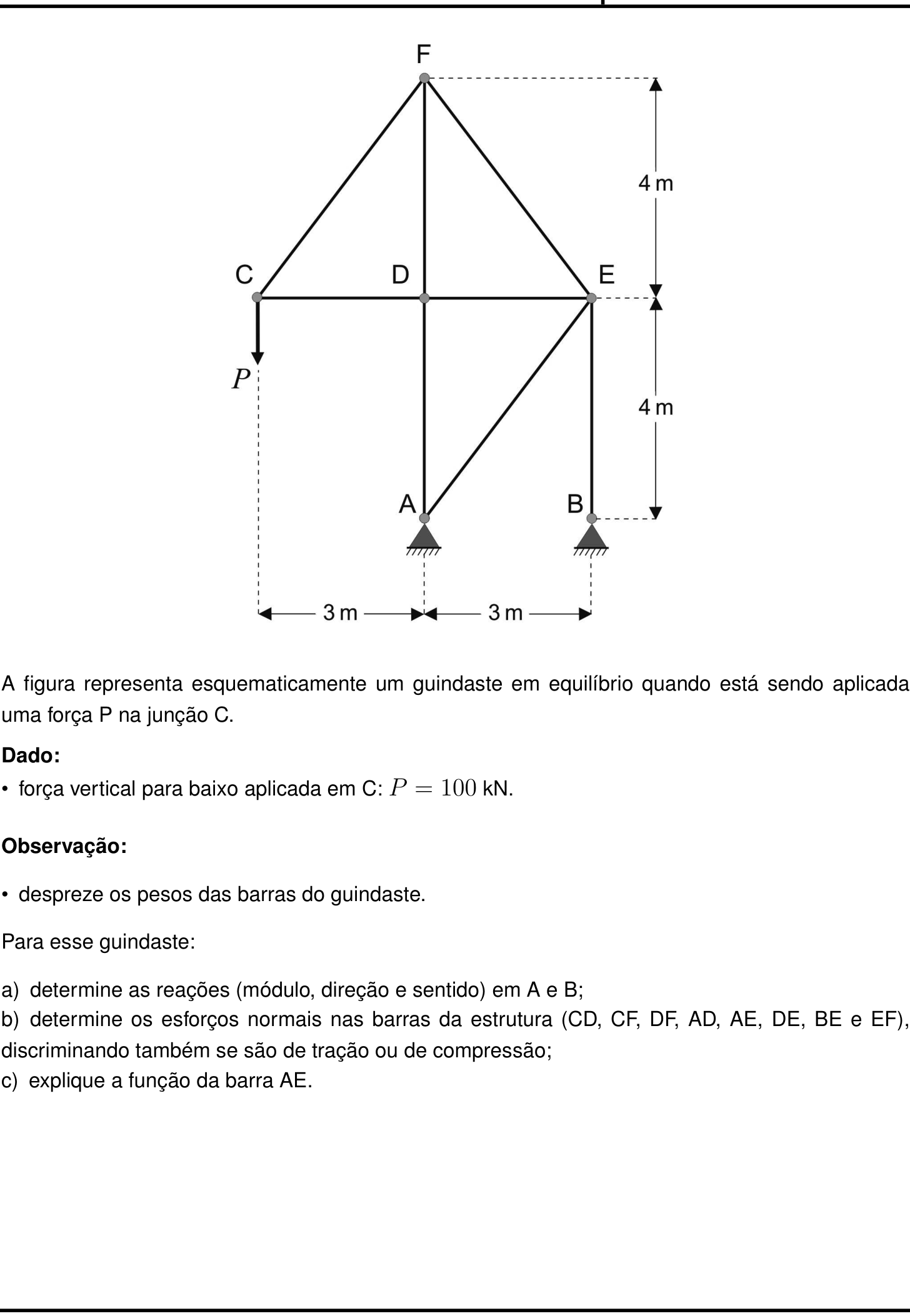
Vou adotar tração positiva e indicar valores negativos como compressão.
Coordenadas adotadas (m): A=(3,0), B=(6,0), C=(0,4), D=(3,4), E=(6,4), F=(3,8).
Assim, as barras inclinadas CF, EF e AE têm comprimento 5\text{ m}, com componentes horizontais 3/5 e verticais 4/5 ou -4/5, conforme o sentido.


a) Reações em A e B

Equilíbrio global, adotando momento positivo no sentido anti-horário:

\sum M_A=0

A carga P=100\text{ kN}, para baixo, dista 3\text{ m} à esquerda de A, produzindo momento:

+100\cdot 3=+300\text{ kN·m}

A reação vertical em B, se para cima, dista 3\text{ m} de A:

+3B_y

Então:

300+3B_y=0 \Rightarrow B_y=-100\text{ kN}

Portanto, B_y tem módulo 100\text{ kN}, direção vertical e sentido para baixo.

Equilíbrio vertical:

\sum F_y=0:\quad A_y+B_y-100=0
A_y-100-100=0 \Rightarrow A_y=200\text{ kN}

Como em B só existe a barra vertical BE, não há componente horizontal de barra, logo:

B_x=0

E por equilíbrio horizontal:

A_x+B_x=0 \Rightarrow A_x=0

Reações:

  • Em A: 200\text{ kN}, vertical, para cima.
  • Em B: 100\text{ kN}, vertical, para baixo.

b) Esforços normais nas barras

Nó C

Barras CD e CF, com carga P=100\text{ kN} para baixo.

\sum F_x=0:\quad T_{CD}+\frac35T_{CF}=0
\sum F_y=0:\quad \frac45T_{CF}-100=0
T_{CF}=125\text{ kN} \quad (\text{tração})
T_{CD}=-\frac35\cdot125=-75\text{ kN} \quad (\text{compressão})

Nó F

\sum F_x=0:\quad -\frac35T_{CF}+\frac35T_{EF}=0
T_{EF}=T_{CF}=125\text{ kN} \quad (\text{tração})
\sum F_y=0:\quad -\frac45T_{CF}-T_{DF}-\frac45T_{EF}=0
-\frac45\cdot125-T_{DF}-\frac45\cdot125=0
-100-T_{DF}-100=0 \Rightarrow T_{DF}=-200\text{ kN} \quad (\text{compressão})

Nó D

\sum F_x=0:\quad -T_{CD}+T_{DE}=0
T_{DE}=T_{CD}=-75\text{ kN} \quad (\text{compressão})
\sum F_y=0:\quad -T_{AD}+T_{DF}=0
T_{AD}=T_{DF}=-200\text{ kN} \quad (\text{compressão})

Nó E

\sum F_x=0:\quad -T_{DE}-\frac35T_{EF}-\frac35T_{AE}=0
-(-75)-\frac35\cdot125-\frac35T_{AE}=0
75-75-\frac35T_{AE}=0 \Rightarrow T_{AE}=0
\sum F_y=0:\quad \frac45T_{EF}-\frac45T_{AE}-T_{BE}=0
\frac45\cdot125-T_{BE}=0 \Rightarrow T_{BE}=100\text{ kN} \quad (\text{tração})

Conferência nos nós A e B

Nó A:

A_x+0,6T_{AE}=0 \Rightarrow A_x=0
T_{AD}+0,8T_{AE}+A_y=0
-200+A_y=0 \Rightarrow A_y=200\text{ kN}

Nó B:

B_x=0
T_{BE}+B_y=0 \Rightarrow 100+B_y=0 \Rightarrow B_y=-100\text{ kN}

Tabela de esforços normais

Barra Esforço normal Natureza
CD 75\text{ kN} compressão
CF 125\text{ kN} tração
DF 200\text{ kN} compressão
AD 200\text{ kN} compressão
AE 0 nula
DE 75\text{ kN} compressão
BE 100\text{ kN} tração
EF 125\text{ kN} tração

c) Função da barra AE

A barra AE é uma diagonal de contraventamento do painel inferior ADEB. Para o carregamento vertical dado, seu esforço normal é nulo, mas ela é importante para garantir a estabilidade e a rigidez da estrutura, impedindo que o painel inferior se torne um mecanismo deformável sob ações horizontais ou cargas assimétricas.

Resposta final: a) A: 200 kN vertical para cima; B: 100 kN vertical para baixo (componentes horizontais nulas); b) CD: 75 kN (compressão), CF: 125 kN (tração), DF: 200 kN (compressão), AD: 200 kN (compressão), AE: 0, DE: 75 kN (compressão), BE: 100 kN (tração), EF: 125 kN (tração); c) barra de contraventamento que garante estabilidade do painel inferior.

Gemini 3.8 Flash

Respondeu · bate com a resposta de referência dos cursinhos

a) Em A: 200 kN, vertical para cima; Em B: 100 kN, vertical para baixo; b) CD: 75 kN (compressão); CF: 125 kN (tração); DF: 200 kN (compressão); AD: 200 kN (compressão); AE: 0; DE: 75 kN (compressão); BE: 100 kN (tração); EF: 125 kN (tração); c) Garantir a indeformabilidade geométrica da treliça (contraventamento do quadrilátero ABED) e transmitir esforços para o apoio A caso atuem cargas horizontais ou dinâmicas.

levou 1 min 20 s

Como pensou
**Analyzing Crane Equilibrium** I'm currently analyzing the provided image, focusing on structural statics principles relevant to cranes and trusses. My immediate task involves carefully dissecting the problem statement, specifically noting the condition of equilibrium under the applied force P. **Examining Support Conditions** My current focus is on precisely defining the support conditions at points A and B. I'm scrutinizing the graphical representations, as the distinct symbols for these supports are crucial for accurately calculating reactions and internal forces. **Clarifying Support Reactions** I'm re-examining the supports at A and B, zooming in closely. It appears B has a roller support (indicated by the inclined hatching below the horizontal line), while A also seems to be a roller or pin, though the details are subtle. I'm confirming the number of bars and nodes (6 nodes) to ensure the structure's static determinacy. **Calculating Support Reactions** I'm recalculating the degree of static indeterminacy, noting there are 6 nodes and 8 bars, suggesting a potential of 4 reactions for static determinacy. I'm focusing on the supports at A and B; B appears to have only a vertical reaction due to the connection with bar BE, while A's reaction components are still under review. **Refining Support Analysis** I'm re-evaluating the support conditions based on a closer look. It seems A is a fixed support ($H_A, V_A$), while B is a roller with only a vertical reaction ($V_B$). This suggests 3 external reactions. However, upon re-counting nodes (6) and bars (8), the equation $b+r = 2n$ doesn't quite balance, prompting a detailed node-by-node re-examination. **Confirming Bar Forces** I'm now focusing on the forces within the structural bars. My current thought process confirms that the reaction at support B is directly equal to the force in bar BE, which simplifies calculations. I'm also evaluating the reactions at support A, considering it a fixed pin. **Confirming Null-Force Bars** I'm re-evaluating my previous assumptions about support A. It seems the horizontal reaction at A, $H_A$, is indeed zero due to the absence of external horizontal forces and the nature of support B. This implies the force in bar AE is also zero, which aligns with the prompt asking about its function. **Confirming Quadrilateral Function** I'm now realizing the crucial role of bar AE. Without it, quadrilateral ABED would be a mechanism, prone to collapse under loads. AE prevents this deformation, acting as a structural stabilizer, and would also resist horizontal forces. **Defining Node Coordinates** I am now precisely defining the coordinates for each node based on the provided dimensions and inferred horizontal/vertical alignments. I've established a coordinate system with A at the origin and am calculating the positions of all other nodes, including F at (0,8). **Verifying Bar Connectivity** I'm systematically checking if the identified bars connect the defined nodes as per the structural diagram. This involves calculating the distances between nodes and comparing them to the expected bar lengths, ensuring consistency with the geometry. **Confirming Structural Properties** My current focus is on verifying the geometric and connectivity properties of the structure. I've established node coordinates and am now confirming that the eight specified bars accurately connect these nodes, ensuring the structural diagram is consistent with the problem's description. **Calculating External Reactions** I have successfully calculated the external reactions at supports A and B. Specifically, I've determined that the horizontal reaction at A is zero, and the vertical reaction at B is equal to the applied force P, pointing upwards. The vertical reaction at A has also been determined. **Revising Reaction Calculations** I'm re-evaluating my moment calculations, specifically concerning the force P relative to support B. It appears my initial assessment of the moment direction was incorrect. I'm meticulously recalculating this, along with the moment contribution from $V_A$ to ensure accuracy in determining all external reactions. **Revising Moment Calculations** I'm meticulously re-calculating the moments, having identified an error in my previous direction assessment. I'm focusing on how the force P creates a counter-clockwise torque around A, and now carefully considering how the reaction at B must counteract this. **Calculating Support Reactions** My current analysis reveals that the moment of force P about A is counter-clockwise. To maintain equilibrium, the reaction at B must create an opposing clockwise moment. This suggests a downward reaction force at B, leading to a significantly larger upward reaction at A. **Calculating Support Reactions** My current analysis reveals that the moment of force P about A is counter-clockwise. To maintain equilibrium, the reaction at B must create an opposing clockwise moment. This suggests a downward reaction force at B, leading to a significantly larger upward reaction at A. **Confirming Force Balance** My calculations for the external reactions at supports A and B are now complete and validated. The moments generated by the applied force P and the reaction at A perfectly balance each other, confirming the horizontal reaction at A is zero. The vertical reaction at B has been determined as 100 kN downwards, and at A as 200 kN upwards, which aligns with the structural stability requirements. **Analyzing Node Forces** I am now calculating the normal forces in each bar using the method of joints. Starting with node B, I've confirmed that the reaction force of 100 kN downwards is balanced by bar BE, resulting in a tensile force of 100 kN within BE. I am now proceeding to analyze node A. **Confirming Null-Force Bars** I'm reconfirming that bar AE has zero normal force, which is fantastic and aligns with prior deductions. Now, analyzing node A with the calculated reactions, I've found that bar AD is under 200 kN of compression. I am proceeding to analyze node C, considering the applied load and the forces from bars CD and CF. **Calculating Bar Forces** I am now calculating the forces within the structural bars using the method of joints, proceeding from node C. I've determined that bar CF is in tension at 125 kN and bar CD is in compression at 75 kN. My next step is to analyze node F to determine the forces in bars EF and DF. **Calculating Remaining Bar Forces** My calculations for the remaining bar forces are nearing completion. I've determined the forces in bars EF and DF, with EF in tension and DF in compression. The force in bar DE is next, and I plan to derive it through the equilibrium equations at node D, with a subsequent check at node E for validation. **Verifying Node D** I have successfully verified the equilibrium at node D. The horizontal forces balance perfectly, confirming that the force in bar DE is indeed equal in magnitude and opposite in direction to the force in bar CD. The vertical forces also balance, indicating that node D is in perfect equilibrium. **Confirming Final Bar Forces** My analysis of node E's equilibrium has yielded perfect results. Both the horizontal and vertical force balances are met exactly using the previously calculated bar forces, confirming their accuracy. The entire structure's internal forces are now precisely determined and verified. **Explaining AE's Role** I'm now focusing on explaining the function of bar AE. It's clear that under the given vertical load, AE experiences zero force. However, I'm detailing how it's crucial for preventing the quadrilateral ABED from becoming a mechanism, thus providing geometric stability and rigidity to the entire truss. **Explaining AE's Role** I'm now focusing on explaining the function of bar AE. It's clear that under the given vertical load, AE experiences zero force. However, I'm detailing how it's crucial for preventing the quadrilateral ABED from becoming a mechanism, thus providing geometric stability and rigidity to the entire truss. I'm also noting its capability to resist horizontal forces and aid in preventing buckling.

Para a resolução da questão, adotamos um sistema de coordenadas com origem no nó A(0, 0):

  • A = (0, 0)\text{ m}
  • B = (3, 0)\text{ m}
  • C = (-3, 4)\text{ m}
  • D = (0, 4)\text{ m}
  • E = (3, 4)\text{ m}
  • F = (0, 8)\text{ m}

A força externa aplicada é \vec{P} = -100\,\hat{j}\text{ kN} em C. O apoio A é uma articulação fixa (reações R_{Ax} e R_{Ay}), e o apoio B é uma articulação móvel / rolete que vincula apenas a direção vertical (reação R_{By}), uma vez que apenas a barra vertical BE concorre em B.


a) Reações nos apoios A e B

Aplicando as equações de equilíbrio estático da estrutura como corpo rígido:

  1. Equilíbrio de forças na horizontal:

    \sum F_x = 0 \implies R_{Ax} = 0

  2. Equilíbrio de momentos em relação ao nó A (adotando o sentido anti-horário como positivo):

    \sum M_A = 0 \implies P \cdot 3\text{ m} + R_{By} \cdot 3\text{ m} = 0

    100 \cdot 3 + 3\,R_{By} = 0 \implies R_{By} = -100\text{ kN}

    O sinal negativo indica que a força aponta para baixo.

  3. Equilíbrio de forças na vertical:

    \sum F_y = 0 \implies R_{Ay} + R_{By} - P = 0

    R_{Ay} + (-100) - 100 = 0 \implies R_{Ay} = 200\text{ kN}

Resultado das reações:

  • No apoio A:
    • Módulo: 200\text{ kN}
    • Direção: vertical
    • Sentido: para cima (\uparrow)
  • No apoio B:
    • Módulo: 100\text{ kN}
    • Direção: vertical
    • Sentido: para baixo (\downarrow)

b) Esforços normais nas barras da estrutura

Adotaremos a convenção de que forças normais positivas representam tração (T) e forças normais negativas representam compressão (C).

  1. Nó B:
    Concorrem a reação vertical R_{By} = -100\text{ kN} (para baixo) e a barra vertical BE.

    \sum F_y = 0 \implies N_{BE} - 100 = 0 \implies N_{BE} = 100\text{ kN}\quad \text{(Tração)}

  2. Nó A:
    Concorrem as reações R_{Ax} = 0, R_{Ay} = 200\text{ kN}, a barra vertical AD e a barra diagonal AE com inclinação dada por \cos\theta = \frac{3}{5} e \sin\theta = \frac{4}{5}.

    \sum F_x = 0 \implies N_{AE} \cos\theta = 0 \implies N_{AE} = 0

    \sum F_y = 0 \implies R_{Ay} + N_{AD} + N_{AE}\sin\theta = 0 \implies 200 + N_{AD} = 0 \implies N_{AD} = -200\text{ kN}\quad \text{(Compressão)}

  3. Nó C:
    Concorrem a carga P = 100\text{ kN} (\downarrow), a barra horizontal CD e a barra diagonal CF (\vec{CF} = (3, 4)\text{ m}, comprimento 5\text{ m}):

    \sum F_y = 0 \implies N_{CF}\left(\frac{4}{5}\right) - P = 0 \implies N_{CF} = 100 \times \frac{5}{4} = 125\text{ kN}\quad \text{(Tração)}

    \sum F_x = 0 \implies N_{CD} + N_{CF}\left(\frac{3}{5}\right) = 0 \implies N_{CD} + 125 \times \frac{3}{5} = 0 \implies N_{CD} = -75\text{ kN}\quad \text{(Compressão)}

  4. Nó F:
    Concorrem as barras CF, EF (ambas com comprimento 5\text{ m} e inclinação 3:4) e a barra vertical DF:

    \sum F_x = 0 \implies -N_{CF}\left(\frac{3}{5}\right) + N_{EF}\left(\frac{3}{5}\right) = 0 \implies N_{EF} = N_{CF} = 125\text{ kN}\quad \text{(Tração)}

    \sum F_y = 0 \implies -N_{DF} - N_{CF}\left(\frac{4}{5}\right) - N_{EF}\left(\frac{4}{5}\right) = 0

    N_{DF} = -2 \times 125 \times \frac{4}{5} = -200\text{ kN}\quad \text{(Compressão)}

  5. Nó D:
    Concorrem as barras CD, DE (horizontais) e AD, DF (verticais):

    \sum F_x = 0 \implies -N_{CD} + N_{DE} = 0 \implies N_{DE} = N_{CD} = -75\text{ kN}\quad \text{(Compressão)}

    (Verificação em y: \sum F_y = N_{DF} - N_{AD} = -200 - (-200) = 0, verificado).

Resumo dos esforços normais:

  • Barra CD: 75\text{ kN} (Compressão)
  • Barra CF: 125\text{ kN} (Tração)
  • Barra DF: 200\text{ kN} (Compressão)
  • Barra AD: 200\text{ kN} (Compressão)
  • Barra AE: 0 (Barra de esforço nulo)
  • Barra DE: 75\text{ kN} (Compressão)
  • Barra BE: 100\text{ kN} (Tração)
  • Barra EF: 125\text{ kN} (Tração)

c) Função da barra AE

Embora a barra AE apresente esforço normal nulo para a condição de carregamento estático puramente vertical aplicada em C, ela desempenha funções essenciais na estrutura:

  1. Rigidez geométrica (indeformabilidade): Ela funciona como elemento de contraventamento que triangula o quadrilátero ABED. Sem a barra AE, o quadrilátero se comportaria como um mecanismo articulado móvel/instável.
  2. Resistência a cargas horizontais e dinâmicas: Caso a estrutura seja submetida a carregamentos não verticais (como ação de ventos, acelerações laterais ou oscilações da carga içada em C), a barra AE é solicitada e transfere os esforços horizontais para o apoio fixo A.

Resposta final:
a) Em A: 200 kN, vertical para cima; Em B: 100 kN, vertical para baixo;
b) CD: 75 kN (compressão); CF: 125 kN (tração); DF: 200 kN (compressão); AD: 200 kN (compressão); AE: 0; DE: 75 kN (compressão); BE: 100 kN (tração); EF: 125 kN (tração);
c) Garantir a indeformabilidade geométrica da treliça (contraventamento do quadrilátero ABED) e transmitir esforços para o apoio A caso atuem cargas horizontais ou dinâmicas.

Gemini 4 Argon

Respondeu · bate com a resposta de referência dos cursinhos

a) Em A: 200 kN, vertical, para cima; em B: 100 kN, vertical, para baixo; b) CD = 75 kN (compressão), CF = 125 kN (tração), DF = 200 kN (compressão), AD = 200 kN (compressão), AE = 0, DE = 75 kN (compressão), BE = 100 kN (tração), EF = 125 kN (tração); c) Garantir a estabilidade e a rigidez geométrica da estrutura contra perturbações ou esforços horizontais.

levou 54 s

Como pensou
**Analyzing Crane Equilibrium** I am currently focused on understanding the forces at play within the crane system, specifically analyzing the equilibrium conditions at junction C. My immediate goal is to determine the magnitude and direction of the applied force $P$ based on the provided diagram and given information. **Calculating Force P** I have determined the coordinates of all the nodes, which has allowed me to calculate the lengths of each bar in the crane structure. This geometric understanding is crucial for the next steps. **Determining Support Reactions** I've confirmed that support B acts as a simple pin connection for bar BE. This simplifies things significantly, as the reaction force at B must be purely vertical and along the line of bar BE. I'm now proceeding with calculating the other reactions at A and B. **Verifying Bar Forces** I've confirmed the support reactions, finding $H_A=0$, $V_A=200 \text{ kN}$ upward, and $V_B=100 \text{ kN}$ downward. Now I am proceeding to calculate the normal forces in each bar using the method of joints, starting with joint C, and assuming tensile forces. **Calculating Bar Forces** I have successfully calculated the forces within bars CD, CF, EF, and DF. Bar CD is in compression at 75 kN, while CF and EF are in tension at 125 kN. Bar DF is in compression at 200 kN. My next step is to analyze joint D. **Analyzing Joint D** I have calculated the forces in bars DE and AD. DE is in compression at 75 kN, and AD is also in compression at 200 kN. My next focus is to analyze joint E. **Explaining Bar AE's Role** I've confirmed all my calculations for support reactions and bar forces, finding everything to be consistent. My current focus is explaining the crucial function of bar AE. Even though its internal force is zero under this specific loading, it's essential for maintaining the overall geometric stability and preventing collapse of the A-B-E-D panel by acting as a bracing element.

a) Determinação das reações nos apoios A e B:

Observando o nó B, nota-se que apenas a barra vertical BE está conectada a ele. Como os pesos das barras são desprezíveis e não há forças externas aplicadas ao longo de BE, esta barra funciona como um elemento de duas forças (sujeito apenas a esforço axial vertical). Consequentemente, a reação no apoio B é puramente vertical (R_{Bx} = 0).

Pelo equilíbrio de forças horizontais na estrutura como um todo:

\sum F_x = 0 \implies R_{Ax} + R_{Bx} = 0 \implies R_{Ax} = 0

Adotando o sentido para cima como positivo para as reações verticais R_{Ay} e R_{By}, aplicamos a condição de equilíbrio de momentos em relação ao apoio A (sentido anti-horário como positivo):

\sum M_A = 0 \implies P \cdot 3 + R_{By} \cdot 3 = 0

100 \cdot 3 + 3 R_{By} = 0 \implies R_{By} = -100\text{ kN}

O sinal negativo indica que a reação em B aponta para baixo.

Pelo equilíbrio de forças verticais na estrutura:

\sum F_y = 0 \implies R_{Ay} + R_{By} - P = 0

R_{Ay} - 100 - 100 = 0 \implies R_{Ay} = 200\text{ kN}

Portanto, as reações nos apoios são:

  • Em A: módulo igual a 200\text{ kN}, direção vertical e sentido para cima.
  • Em B: módulo igual a 100\text{ kN}, direção vertical e sentido para baixo.

b) Determinação dos esforços normais nas barras:

Pela geometria da treliça, as barras inclinadas (CF, EF e AE) estão inseridas em triângulos retângulos de catetos horizontal 3\text{ m} e vertical 4\text{ m} (hipotenusa de 5\text{ m}). Sendo \theta o ângulo que essas barras formam com a horizontal, temos:

\cos\theta = \frac{3}{5} = 0,6 \quad \text{e} \quad \operatorname{sen}\theta = \frac{4}{5} = 0,8

Adotando a convenção de que todas as forças normais incógnitas saem dos nós (tração positiva):

  • Nó C:

    \sum F_y = 0 \implies N_{CF}\operatorname{sen}\theta - P = 0 \implies N_{CF} \cdot 0,8 = 100 \implies N_{CF} = 125\text{ kN (Tração)}

    \sum F_x = 0 \implies N_{CD} + N_{CF}\cos\theta = 0 \implies N_{CD} + 125 \cdot 0,6 = 0 \implies N_{CD} = -75\text{ kN} \implies 75\text{ kN (Compressão)}

  • Nó F:

    \sum F_x = 0 \implies N_{EF}\cos\theta - N_{CF}\cos\theta = 0 \implies N_{EF} = N_{CF} = 125\text{ kN (Tração)}

    \sum F_y = 0 \implies -N_{DF} - N_{CF}\operatorname{sen}\theta - N_{EF}\operatorname{sen}\theta = 0 \implies N_{DF} = -2 \cdot 125 \cdot 0,8 = -200\text{ kN} \implies 200\text{ kN (Compressão)}

  • Nó D:
    Como as barras CD e DE são colineares na horizontal e as barras DF e AD são colineares na vertical:

    \sum F_x = 0 \implies N_{DE} - N_{CD} = 0 \implies N_{DE} = N_{CD} = -75\text{ kN} \implies 75\text{ kN (Compressão)}

    \sum F_y = 0 \implies N_{DF} - N_{AD} = 0 \implies N_{AD} = N_{DF} = -200\text{ kN} \implies 200\text{ kN (Compressão)}

  • Nó E:

    \sum F_x = 0 \implies -N_{DE} - N_{EF}\cos\theta - N_{AE}\cos\theta = 0

    -(-75) - 125 \cdot 0,6 - N_{AE} \cdot 0,6 = 0 \implies 75 - 75 - 0,6 N_{AE} = 0 \implies N_{AE} = 0\text{ (Barra sem esforço)}

    \sum F_y = 0 \implies N_{EF}\operatorname{sen}\theta - N_{AE}\operatorname{sen}\theta - N_{BE} = 0

    125 \cdot 0,8 - 0 - N_{BE} = 0 \implies N_{BE} = 100\text{ kN (Tração)}

Resumo dos esforços nas barras:

  • CD: 75\text{ kN} (compressão)
  • CF: 125\text{ kN} (tração)
  • DF: 200\text{ kN} (compressão)
  • AD: 200\text{ kN} (compressão)
  • AE: 0\text{ kN} (nulo)
  • DE: 75\text{ kN} (compressão)
  • BE: 100\text{ kN} (tração)
  • EF: 125\text{ kN} (tração)

c) Função da barra AE:

Embora a barra AE não sofra esforço normal sob o carregamento estático puramente vertical considerado (N_{AE} = 0), ela é indispensável para garantir a estabilidade geométrica (rigidez) da estrutura (estabilidade do equilíbrio). Sem a barra AE, o quadrilátero ABED formaria um mecanismo (paralelogramo articulado hipostático), e o guindaste entraria em colapso lateral diante de qualquer perturbação horizontal, como a ação de ventos ou oscilações laterais da carga P.

Resposta final: a) Em A: 200 kN, vertical, para cima; em B: 100 kN, vertical, para baixo; b) CD = 75 kN (compressão), CF = 125 kN (tração), DF = 200 kN (compressão), AD = 200 kN (compressão), AE = 0, DE = 75 kN (compressão), BE = 100 kN (tração), EF = 125 kN (tração); c) Garantir a estabilidade e a rigidez geométrica da estrutura contra perturbações ou esforços horizontais.

GPT-6.1 Terra

Respondeu · bate com a resposta de referência dos cursinhos

a) A=200\ \text{kN} para cima; B=100\ \text{kN} para baixo; b) em kN: CD 75 C, CF 125 T, DF 200 C, AD 200 C, AE 0, DE 75 C, BE 100 T, EF 125 T; c) contraventamento.

levou 38 s

Como pensou
**Analyzing a mechanism** I'm examining a parallelogram formed by rectangle ABED, where AB equals 3. It's part of a four-bar mechanism, and point D/E moves in a circular arc along fixed-length AD/BE while DE stays horizontal. When folded, the rectangle turns into a parallelogram. The diagonal AE stabilizes the structure, but under vertical load C, AE's function becomes zero. This leads me to wonder if the structure can still function without AE, raising questions about its equilibrium.

Adotemos forças normais positivas para tração e negativas para compressão. As barras inclinadas têm projeções horizontal e vertical na razão 3:4, sendo seus cossenos diretores 3/5 e 4/5.

a) Reações nos apoios

Na junção B, a única barra é vertical; portanto, B_x=0. Pelo equilíbrio horizontal da estrutura, A_x=0.

Tomando momentos em relação a A e, depois, equilibrando as forças verticais:

100\cdot3+B_y\cdot3=0 \quad\Rightarrow\quad B_y=-100\ \text{kN},
A_y+B_y-100=0 \quad\Rightarrow\quad A_y=200\ \text{kN}.

Assim, a reação em A é vertical para cima, de 200\ \text{kN}, e a reação em B é vertical para baixo, de 100\ \text{kN}. Esta última exige que o apoio em B resista ao arrancamento.

b) Esforços nas barras

Na junção C:

\frac45N_{CF}-100=0 \quad\Rightarrow\quad N_{CF}=125\ \text{kN},
N_{CD}+\frac35N_{CF}=0 \quad\Rightarrow\quad N_{CD}=-75\ \text{kN}.

Na junção A:

\frac35N_{AE}=0 \quad\Rightarrow\quad N_{AE}=0,
200+N_{AD}+\frac45N_{AE}=0 \quad\Rightarrow\quad N_{AD}=-200\ \text{kN}.

Na junção D, o equilíbrio horizontal e o vertical dão, respectivamente,

N_{DE}=N_{CD}=-75\ \text{kN}, \qquad N_{DF}=N_{AD}=-200\ \text{kN}.

Na junção F, o equilíbrio horizontal fornece

N_{EF}=N_{CF}=125\ \text{kN}.

Por fim, na junção B,

-100+N_{BE}=0 \quad\Rightarrow\quad N_{BE}=100\ \text{kN}.

Logo:

Barra Esforço Natureza
CD 75\ \text{kN} compressão
CF 125\ \text{kN} tração
DF 200\ \text{kN} compressão
AD 200\ \text{kN} compressão
AE 0 nulo
DE 75\ \text{kN} compressão
BE 100\ \text{kN} tração
EF 125\ \text{kN} tração

c) Função da barra AE

A barra AE contraventa a estrutura: ela triangula o quadrilátero ABED, impedindo seu deslocamento lateral como mecanismo articulado. Embora essencial para a estabilidade, não é solicitada pelo carregamento particular indicado.

Resposta final: a) A=200\ \text{kN} para cima; B=100\ \text{kN} para baixo; b) em kN: CD 75 C, CF 125 T, DF 200 C, AD 200 C, AE 0, DE 75 C, BE 100 T, EF 125 T; c) contraventamento.