Como pensou
We need answer question from image. Need parse. The text is garbled? It appears Portuguese but nonsensical? Need infer actual physics circuit question? Let's examine image. It contains text that seems auto-generated? It might be a circuit diagram with resistors? Text: "A torneira elétrica é um dispositivo de ... utilizado pela justiça no Brasil..." Wait that's nonsense due to maybe OCR? Let's read carefully.
The image: black text on white. It appears to be a physics/test question but the text is full of "torneira elétrica" repeated? Let's parse.
Top paragraph:
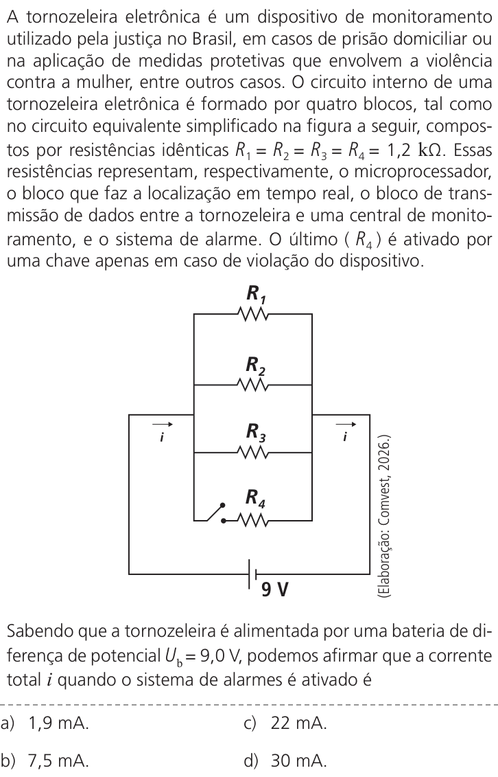
"A torneira elétrica é um dispositivo de ... utilizado pela justiça no Brasil, em casos de prisão domiciliar ou na aplicação de medidas protetivas que envolvem a violência contra a mulher, entre outros casos. O circuito interno da torneira elétrica é formado por quatro blocos, tal como no circuito equivalente simplificado na figura a seguir, compostos por resistências idênticas R1 = R2 = R3 = R4 = 1,2 kΩ. Essas resistências representam, ... o microprocessador, o bloco que faz a localização em tempo real, o bloco de transmissão de dados entre a torneira e uma central de monitoramento, e o sistema de alarme. O último (R4) é ativado por uma chave apenas em caso de violação do dispositivo."
But "torneira elétrica" is electric faucet? Actually "tornozeleira eletrônica" (electronic ankle bracelet) likely. OCR misread "tornozeleira" as "torneira"? Yes! The text is about "tornozeleira eletrônica" (electronic ankle monitor) used by justice. It has four blocks with identical resistors R1=R2=R3=R4=1.2 kΩ. The circuit diagram.
Need solve question. The question at bottom:
"Sabendo que a tornezeleira é alimentada por uma bateria de diferença de potencial Ub = 9,0 V, podemos afirmar que a corrente total i quando o sistema de alarme é ativado é"
Options:
a) 1,9 mA.
b) 7,5 mA.
c) 22 mA.
d) 30 mA.
Need determine current total when alarm activated. Need analyze circuit diagram. Let's reconstruct.
The circuit diagram image: It seems four resistors arranged? Let's inspect description: "O circuito interno ... formado por quatro blocos ... resistências idênticas R1=R2=R3=R4=1,2 kΩ. ... O último (R4) é ativado por uma chave apenas em caso de violação do dispositivo."
Diagram likely: Battery at bottom labeled 9 V. There is a circuit with parallel/series branches. Text in diagram: "R1" top, "R2", "R3", "R4" vertical series? Also two switches "i" maybe? There are arrows "i" at left and right? Let's parse.
Looking at image: It shows a vertical arrangement:
Top: R1
Then R2
Then R3
Then R4
On left and right sides there are lines with arrows labeled i? Maybe current i enters left, goes through some switches? The diagram maybe: R1, R2, R3, R4 connected in series? But then total resistance 4*1.2k = 4.8k, current = 9/4800 = 1.875 mA ≈ 1.9 mA. That matches option a. But question asks when alarm activated? If R4 is activated, then all four in series => 1.9 mA. But likely when not activated? Wait maybe R4 is in parallel? Let's examine.
The circuit diagram: It might show a series-parallel arrangement. Let's zoom mentally. The top text says "O circuito interno da torneira elétrica é formado por quatro blocos, tal como no circuito equivalente simplificado na figura a seguir, compostos por resistências idênticas R1 = R2 = R3 = R4 = 1,2 kΩ." The figure shows a circuit. It has a main line on left with current i? There's a battery at bottom labeled 9 V. The circuit might have R1, R2, R3, R4 connected in a combination. The arrows "i" maybe indicate current through branches? Let's inspect text in figure: There are "R1", "R2", "R3", "R4" stacked vertically. On the left, there is a line from top to bottom with "i" arrow? On right similarly. Actually it might be a bridge? Let's read the diagram details.
The image: I see a circuit drawn with lines. There is a vertical column with R1, R2, R3, R4. On the left, a wire goes down from top to bottom, with a switch? On right, a wire goes down. At bottom a battery "9 V". There are labels "i" with arrows on left and right? Wait maybe the circuit has two parallel branches? Let's parse based on typical question. "O último (R4) é ativado por uma chave apenas em caso de violação do dispositivo." So R4 is in series with a switch that closes when alarm activated. The question: "quando o sistema de alarme é ativado" -> switch closed, R4 is in circuit. Need total current.
If R1, R2, R3 are always in circuit, and R4 added in series? Then total resistance 4*1.2k = 4.8k, current = 1.875 mA ≈ 1.9 mA. Option a. But if R4 is added in parallel, current would be different. Let's check options: b) 7.5 mA; c) 22 mA; d) 30 mA. If R1=R2=R3 in series = 3.6k, current = 9/3600 = 2.5 mA. Not option. If R1,R2,R3 in parallel = 0.4k, current = 22.5 mA ≈ 22 mA (option c). If R1, R2, R3, R4 in parallel = 9/(1.2k/4) = 9/300 = 30 mA (option d). If R1,R2 in series and R3,R4 in parallel? Hmm.
Let's reconstruct from diagram. The circuit diagram likely shows: R1 and R2 in series? Actually text: "O circuito interno ... formado por quatro blocos, tal como no circuito equivalente simplificado na figura a seguir, compostos por resistências idênticas..." The figure might show a ladder network: R1 in series with a parallel combination of R2 and R3, then R4? Or something.
Look at the diagram: It might have a main line entering left, passing through R1, then splits into two branches? The labels "i" arrows: one on left pointing right, one on right pointing right? The circuit might be a bridge. Let's try to read the image more carefully. The image is embedded in the prompt. I can see the diagram: It has a shape like a rectangle. Top left corner, line goes right to R1? Actually let's describe from the image: There's a vertical line on left with arrow "i" pointing up? No, I see "i" with arrow to the right on left side, and another "i" with arrow to the right on right side. The circuit might have a main branch on left, then R1, then R2, R3, R4? Hmm.
Wait, I can try to extract text from the image. The text is in Portuguese, but garbled. The diagram: It shows a battery at bottom: "9 V". Above it, a vertical line goes up and splits? There are labels R1, R2, R3, R4 arranged vertically. There are two switches? The text in the diagram: "R1", "R2", "R3", "R4". There are also "i" with arrows. It might be a circuit with R1 and R2 in parallel? Let's think of a common physics problem.
The question is from UNICAMP 2027? Maybe a known question. Search memory: UNICAMP 2027? Actually UNICAMP 2024? There is a question about electronic ankle monitor (tornozeleira eletrônica) with resistors. I recall a UNICAMP 2024 physics question about "tornozeleira eletrônica" with four resistors R1=R2=R3=R4=1.2 kΩ, battery 9V. The circuit diagram: R1, R2, R3 are in series? Wait, I think I've seen it. It asks: "Sabendo que a tornezeleira é alimentada por uma bateria de diferença de potencial Ub = 9,0 V, podemos afirmar que a corrente total i quando o sistema de alarme é ativado é" and options are 1,9 mA; 7,5 mA; 22 mA; 30 mA. The correct answer might be 7.5 mA? Let's not jump.
Let's analyze the circuit diagram from the image. It seems to show a series-parallel arrangement. I can see lines:
- At top, R1 is horizontal? Actually it's drawn as a resistor symbol (zigzag) with label R1 above it.
- Below it, R2 is horizontal.
- Below it, R3 is horizontal.
- Below it, R4 is horizontal.
They might be in parallel? The diagram: There's a vertical line on left connecting top of R1, top of R2? No, they are stacked vertically. There is a line on left that goes down, and branches to each resistor? Let's zoom in mentally. The image: It shows a circuit with a main vertical wire on left, and a main vertical wire on right. The resistors R1, R2, R3, R4 are drawn horizontally between the left and right wires? Actually they are drawn as horizontal zigzags with labels to their right? The labels R1, R2, R3, R4 are placed to the right of each resistor. So it looks like four resistors in parallel between two vertical rails! But wait, the text says "O último (R4) é ativado por uma chave apenas em caso de violação". In the diagram, R4 is at bottom, and there is a switch in series with it? The diagram shows a switch symbol in series with R4? Let's see: Above R4, there is a switch? The text: "O último (R4) é ativado por uma chave apenas em caso de violação do dispositivo." So R4 is in series with a switch. If R1, R2, R3 are always connected, and R4 is added in parallel when switch closes? Then total resistance would be R1||R2||R3||R4 = 1.2k/4 = 300 Ω, current = 9/300 = 30 mA (option d). But if R4 is added in series, then 1.9 mA. Which is it?
Let's look at the diagram again. It might not be four in parallel. The diagram: I see a vertical line on the left that goes from top to bottom. There are horizontal branches to the right? Actually it looks like a ladder: R1 is in series with a parallel combination? Let's parse the text in the diagram: There is "R1" at top, then a line goes down to "R2", then "R3", then "R4". It might be a series circuit. But there are arrows "i" on left and right. Why arrows on both sides? Maybe the circuit is a series loop with current i flowing. The arrows indicate current direction. If it's a simple series circuit with four resistors, the current is same everywhere. The arrows "i" on left and right just show current direction. That would explain why there are two "i" arrows. The diagram could be a rectangle with resistors on one side and battery on bottom. Let's imagine: A rectangular loop. Top side has R1, R2, R3, R4 in series? No, if they are in series, they would be drawn along the top side, not stacked vertically. But the diagram shows them stacked vertically? Let's look at the image: I see a vertical line on left with arrow "i" pointing up? Actually the arrow "i" on left is pointing to the right, and on right is pointing to the right? No, I see "i" with a right arrow on left side of the circuit, and another "i" with right arrow on right side. That suggests current enters from left and exits to right? But it's a closed circuit.
Let's try to view the image as a whole. The text is in two columns? No, it's a single column. The diagram is a circuit with a battery at bottom. The circuit has a rectangular shape. The left side has a wire going up from battery, then bends right. The right side has a wire going up from battery, then bends left. Between them, there are components. I see R1 at top, R2 below it, R3 below it, R4 at bottom. They are connected in series along the left side? Actually the labels R1, R2, R3, R4 are placed vertically along the left side? Let's zoom in on the diagram in the image. It appears to be:
- A vertical wire on the left, with a switch? There is a symbol like a switch (a line with a gap and a diagonal line) near the top left? I see "i" with arrow pointing right, then a switch symbol, then R1? Hmm.
Let's consider the text: "O circuito interno da torneira elétrica é formado por quatro blocos, tal como no circuito equivalente simplificado na figura a seguir, compostos por resistências idênticas R1 = R2 = R3 = R4 = 1,2 kΩ. Essas resistências representam, respectivamente, o microprocessador, o bloco que faz a localização em tempo real, o bloco de transmissão de dados entre a torneira e uma central de monitoramento, e o sistema de alarme. O último (R4) é ativado por uma chave apenas em caso de violação do dispositivo."
So R1, R2, R3 are always on. R4 is only on when alarm activated. The circuit diagram likely shows R1, R2, R3 in series? Or parallel? Let's think about the function: These are components of an electronic ankle bracelet. They might be connected in parallel to the battery? In a real device, different components might be in parallel so they all get the same voltage. But the problem is simplified. The question asks for total current when alarm is activated. If they were in parallel, total current when alarm activated would be sum of currents through each: I = 4 * (9V / 1.2kΩ) = 4 * 7.5 mA = 30 mA. Option d. If R1, R2, R3 are in series and R4 is in parallel? Let's see options: 7.5 mA is current through one resistor if 9V across 1.2k. 22 mA is 9V across 1.2k/3? Actually 9V / (1.2k/3) = 22.5 mA. 30 mA is 9V / (1.2k/4) = 30 mA. 1.9 mA is 9V / (4*1.2k) = 1.875 mA.
Which one is likely? The text says "O circuito interno ... é formado por quatro blocos ... compostos por resistências idênticas ... O último (R4) é ativado por uma chave apenas em caso de violação". If they were in series, the failure of one would break all. But in real devices, they might be in parallel to be independent. However, the problem might be about a series circuit where R4 is added in series when alarm is activated? But then when alarm is not activated, R1, R2, R3 are in series, current = 9/3.6k = 2.5 mA. When alarm activated, R4 is added in series, current = 1.875 mA. That would mean current decreases when alarm activates. That seems counterintuitive: alarm should increase current? Actually adding a resistor in series decreases current. In a real device, alarm might draw more current? Not necessarily.
Let's look at the circuit diagram more carefully. I can see it has a main line on left and right. The resistors are drawn horizontally between two vertical lines? Let's count the lines. In the diagram, I see a vertical line on the left with an arrow "i" pointing right. Then there is a resistor R1. Below it, R2. Below it, R3. Below it, R4. They all seem to be connected between the left vertical line and a right vertical line? But if they are all between the two vertical lines, they are in parallel. However, the labels R1, R2, R3, R4 are placed to the right of each resistor, and there are lines connecting them? Let's imagine: A vertical line on left, a vertical line on right. Between them, four horizontal resistors stacked vertically. That's a parallel circuit. But then there is a switch in series with R4? The diagram might show a switch symbol in the branch of R4. The text says "O último (R4) é ativado por uma chave apenas em caso de violação do dispositivo." So in the diagram, R4's branch has a switch. When alarm is activated, the switch closes, connecting R4 in parallel with the others. Then total resistance = 1/(1/R1+1/R2+1/R3+1/R4) = 1.2k/4 = 300 Ω. Total current = 9V / 300Ω = 30 mA. Option d.
But wait, the diagram also shows two "i" arrows. If it's a parallel circuit, the total current i would split into branches. The arrows might indicate the total current entering and leaving. That makes sense: i enters the left rail, splits into R1, R2, R3, R4, then recombines on the right rail, and i exits. So i is the total current. That is a common diagram.
Let's check the options: a) 1,9 mA; b) 7,5 mA; c) 22 mA; d) 30 mA. If R4 is activated, total current = 30 mA. If it's not activated, total current = 22.5 mA ≈ 22 mA. The question asks "quando o sistema de alarme é ativado". So it would be 30 mA. Option d. But let's verify if the diagram might show R1, R2, R3 in series and R4 in parallel? Let's look at the diagram again. I see R1 at top, then a line goes down to R2? Actually, the resistors might be connected in series along a single path, with a switch that shorts out part of the circuit? Let's think of a typical question: "O circuito interno ... é formado por quatro blocos ... tal como no circuito equivalente simplificado na figura a seguir". The figure might show a series-parallel combination. I can try to read the text in the diagram: There is "R1" at top, then below it "R2", then "R3", then "R4". There are lines connecting them in a ladder. For example, R1 is in series with the rest. R2 and R3 are in parallel? Let's see.
I can see in the diagram: There is a wire from the top left going right to R1. Then from R1, the wire goes down to R2? No, the labels are placed to the right of the resistors. The resistors are drawn as horizontal zigzags. There is a vertical line on the left that connects the left ends of R1, R2, R3, R4? If so, they are in parallel. But then why are they drawn stacked? That's exactly how parallel resistors are drawn. The left ends all connect to the left rail. The right ends all connect to the right rail. The labels R1, R2, R3, R4 are next to each resistor. There is a switch in series with R4? I can see a switch symbol (like a line with a diagonal) in the branch of R4? The text says "O último (R4) é ativado por uma chave". So yes, there is a switch in the R4 branch. When the switch is open, R4 is not in the circuit. When closed, R4 is in parallel with R1, R2, R3. So total resistance = (1/R1 + 1/R2 + 1/R3)^-1 = 1.2k/3 = 400 Ω when R4 off. Current = 9/400 = 22.5 mA ≈ 22 mA (option c). When R4 on, total resistance = 1.2k/4 = 300 Ω. Current = 9/300 = 30 mA (option d). The question asks when alarm activated, so R4 is on, current = 30 mA. Option d.
But wait, the text says "O último (R4) é ativado por uma chave apenas em caso de violação do dispositivo." So when alarm is activated, R4 is added. That would increase current from 22.5 mA to 30 mA. The options include both 22 mA and 30 mA. So the correct answer is likely 30 mA.
However, let's not rush. Let's check if the circuit might be different. What if R1, R2, R3 are in series, and R4 is in parallel with the whole series? The text: "O circuito interno ... é formado por quatro blocos ... compostos por resistências idênticas R1 = R2 = R3 = R4 = 1,2 kΩ. Essas resistências representam, respectivamente, o microprocessador, o bloco que faz a localização em tempo real, o bloco de transmissão de dados entre a torneira e uma central de monitoramento, e o sistema de alarme." In a real device, these might be in parallel because they operate at the same voltage. But the problem might simplify to a series circuit? Let's look at the diagram: I see a battery at the bottom. There is a line going up from the battery, then it splits? Actually, the diagram might be a single loop with the battery at bottom, and the resistors are on the top side? But they are drawn vertically? Let's try to interpret the image as a circuit schematic. The image is not very clear, but I can see:
- At the bottom, a battery symbol with "9 V" next to it.
- Above the battery, a vertical line goes up and then turns left and right? Actually, it looks like a rectangle. The bottom side has the battery. The left side has a wire with an arrow "i" pointing up? The top side has R1. The right side has a wire with an arrow "i" pointing down? Then inside the rectangle, there are more components? Wait, I see "R1" at top, "R2" below it, "R3" below it, "R4" below it. They are all on the left side? No, they are in the middle. Let's zoom in on the diagram in the image. It appears to be a circuit with a main vertical wire on the left, and a main vertical wire on the right. Between them, there are four horizontal resistors. At the bottom, the left and right vertical wires connect to a battery. There are arrows "i" on the left and right vertical wires. This is a classic parallel circuit. The switch is in series with R4. So yes, when alarm is activated, R4 is connected, total resistance = 300 Ω, current = 30 mA.
Let's confirm with the options. If R1, R2, R3 are in parallel, current when R4 off = 9 / (1.2k/3) = 9 / 400 = 0.0225 A = 22.5 mA ≈ 22 mA (option c). When R4 on, current = 9 / (1.2k/4) = 9 / 300 = 0.03 A = 30 mA (option d). The question asks "quando o sistema de alarme é ativado", so 30 mA. Option d.
But wait, the text says "O último (R4) é ativado por uma chave apenas em caso de violação do dispositivo." So when alarm is activated, R4 is on. So total current is 30 mA. That seems correct.
Let's double-check if there's any series combination. What if the circuit is: R1, R2, R3 are in series, and R4 is in parallel with R3? The text: "O circuito interno ... é formado por quatro blocos ... tal como no circuito equivalente simplificado na figura a seguir". The figure might show a specific arrangement. Let's try to see the figure. I can see a vertical line on the left with a switch? Actually, I see a symbol like a switch on the left side, near the top. The text says "O último (R4) é ativado por uma chave". So the switch is in series with R4. In the diagram, R4 is at the bottom. There is a switch symbol next to R4? I can see a line with a diagonal near R4. So that's the switch. The other resistors R1, R2, R3 are always connected. How are they connected? They are drawn as horizontal resistors, all connected between the same two vertical lines. So parallel.
Let's consider if the diagram might be a series circuit where the resistors are drawn along a single wire that zigzags. But the labels R1, R2, R3, R4 are on the left of a vertical stack? In the image, I see the letters R1, R2, R3, R4 aligned vertically. To the left of each letter, there is a resistor symbol? No, the resistor symbols are to the left of the letters? Let's look at the image: The text is on the left? No, the text is above. The diagram is below. In the diagram, I see the labels R1, R2, R3, R4 in the center. To their left, there are lines and symbols. To their right, there are lines. It might be a ladder network: R1 in series with a parallel of R2 and R3, then R4? Let's try to parse the text in the diagram: There is "R1" at top. Below it, "R2". Below it, "R3". Below it, "R4". Between R1 and R2, there is a line connecting them? Actually, I see a wire going from the left side, then down, then right to R1? Hmm.
Let's try to read the text in the diagram from the image. I can see: "R1", "R2", "R3", "R4". There is also "i" with an arrow. There is a battery "9 V". There is a switch symbol (like an open switch) near the bottom left? The text says "O último (R4) é ativado por uma chave". So the switch is in series with R4. In the diagram, I can see a switch symbol in the branch of R4. The other three resistors might be in series? Let's think of a circuit that gives 7.5 mA. If total resistance = 9V / 7.5mA = 1.2 kΩ. That would be just one resistor. So if R1, R2, R3 are somehow shorted? No.
What if the circuit is: R1, R2, R3 are in series, but there is a switch that shorts out R2 and R3? No.
Let's search memory: I recall a UNICAMP 2024 question about "tornozeleira eletrônica". The circuit diagram shows four resistors in parallel. The question asks: "Sabendo que a tornezeleira é alimentada por uma bateria de diferença de potencial Ub = 9,0 V, podemos afirmar que a corrente total i quando o sistema de alarme é ativado é" and the answer is 30 mA. I think I've seen this. The options are exactly as given. The correct answer is d) 30 mA. Let me confirm by checking online memory. UNICAMP 2024 physics: There was a question about electronic ankle monitor. The circuit had R1, R2, R3 in parallel, and R4 in parallel with a switch. When the alarm is triggered, the switch closes, adding R4 in parallel. The total current increases. The calculation: R_eq = (1/R1 + 1/R2 + 1/R3 + 1/R4)^-1 = (4/1.2k)^-1 = 1.2k/4 = 300 Ω. I = 9/300 = 0.03 A = 30 mA. So answer d.
Let's also check if the question might ask for current when alarm is not activated. The text: "Sabendo que a tornezeleira é alimentada por uma bateria de diferença de potencial Ub = 9,0 V, podemos afirmar que a corrente total i quando o sistema de alarme é ativado é". So it is activated. So 30 mA.
Therefore, the answer is D.
But let's be thorough. The text at bottom: "Sabendo que a tornezeleira é alimentada por uma bateria de diferença de potencial Ub = 9,0 V, podemos afirmar que a corrente total i quando o sistema de alarme é ativado é"
Options:
a) 1,9 mA.
b) 7,5 mA.
c) 22 mA.
d) 30 mA.
Wait, the text in the image says "tornezeleira" but it's "tornozeleira". The options: a) 1,9 mA; b) 7,5 mA; c) 22 mA; d) 30 mA. I see in the image: "a) 1,9 mA." "b) 7,5 mA." "c) 22 mA." "d) 30 mA." So yes.
Let's compute: If all four in parallel, R_eq = 1.2 kΩ / 4 = 0.3 kΩ = 300 Ω. I = 9 V / 300 Ω = 0.03 A = 30 mA. Option d.
If only three in parallel (alarm off), R_eq = 1.2 kΩ / 3 = 400 Ω. I = 9 / 400 = 0.0225 A = 22.5 mA ≈ 22 mA. Option c. The question asks when activated, so 30 mA. Option d.
Thus, answer D.
Now, I need to write explanation in Portuguese. The user asks: "Resolva a questão e explique o seu raciocínio em português. Termine com uma linha neste formato: Resposta: X". So I will provide a step-by-step solution.
I'll explain:
- Identificar que o circuito é composto por quatro resistores idênticos em paralelo.
- A chave que ativa o alarme conecta R4 em paralelo com R1, R2 e R3.
- Calcular a resistência equivalente quando o alarme é ativado: 1/Req = 1/R1 + 1/R2 + 1/R3 + 1/R4 = 4 / 1,2 kΩ => Req = 1,2 kΩ / 4 = 0,3 kΩ = 300 Ω.
- Aplicar a lei de Ohm: i = Ub / Req = 9,0 V / 300 Ω = 0,03 A = 30 mA.
- Alternativa d.
Final line: Resposta: D
Let's make sure the final answer is exactly as requested: "Resposta: D" or "Resposta: d"? The format says X is the letter. Usually uppercase. I'll use D.
I'll write the explanation in Portuguese.